
Datasheet


LTM4644/LTM4644-1
16
Rev. F
For more information www.analog.com
APPLICATIONS INFORMATION
Temperature Monitoring
A diode connected PNP transistor is used for the TEMP
monitor function by monitoring its voltage over tempera
-
ture. The temperature dependence of this diode voltage
can be understood in the equation:
V
D
=nV
T
ln
I
D
I
S
⎛
⎝
⎜
⎞
⎠
⎟
where V
T
is the thermal voltage (kT/q), and n, the ideality
factor, is 1 for the diode connected PNP transistor be-
ing used
in the LTM4644. I
S
is expressed by the typical
empirical equation:
I
S
=I
0
exp
–V
G0
V
T
⎛
⎝
⎜
⎞
⎠
⎟
where I
0
is a process and geometry dependent current, (I
0
is typically around 20k orders of magnitude larger than I
S
at room temperature) and V
G0
is the band gap voltage of
1.2V extrapolated to absolute zero or –273°C.
If we take the I
S
equation and substitute into the V
D
equa-
tion, then we get:
V
D
= V
G0
–
kT
q
⎛
⎝
⎜
⎞
⎠
⎟
ln
I
0
I
D
⎛
⎝
⎜
⎞
⎠
⎟
, V
T
=
kT
q
The expression shows that the diode voltage decreases
(linearly if I
0
were constant) with increasing temperature
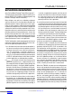
and constant diode current. Figure 6 shows a plot of V
D
vs Temperature over the operating temperature range of
the LTM4644.
If we take this equation and differentiate it with respect to
temperature T, then:
dV
D
dT
= –
V
G0
– V
D
T
This dV
D
/dT term is the temperature coefficient equal to
about –2mV/K or –2mV/°C. The equation is simplified for
the first order derivation.
Solving for T, T = –(V
G0
– V
D
)/(dV
D
/dT) provides the
temperature.
1st Example: Figure 7 for 27°C, or 300K the diode
voltage is 0.598V, thus, 300K = –(1200mV – 598mV)/
–2.0 mV/K)
2
nd Example: Figure 7 for 75°C, or 350K the diode
voltage is 0.50V, thus, 350K = –(1200mV – 500mV)/
–2.0mV/K)
Converting the Kelvin scale to Celsius is simply taking the
Kelvin temp and subtracting 273 from it.
A typical forward voltage is given in the electrical charac
-
teristics section
of the data sheet, and Figure 7 is the plot
of this forward voltage. Measure this forward voltage at
27°C to establish a reference point. Then using the above
expression while measuring the forward voltage over
temperature will provide a general temperature monitor.
Connect a resistor between TEMP and V
IN
to set the cur-
rent to 100µA. See Figure 35 for an example.
Figure 7. Diode Voltage V
D
vs Temperature T(°C)
TEMPERATURE (°C)
–50 –25
0.3
DIODE VOLTAGE (V)
0.5
0.8
0
50
75
0.4
0.7
0.6
25
100
4637 F07
125
I
D
= 100µA
Thermal Considerations and Output Current Derating
The thermal resistances reported in the Pin Configura-
tion section
of the data sheet are consistent with those
parameters defined by JESD 51-12 and are intended for
use with finite element analysis (FEA) software modeling
tools that leverage the outcome of thermal modeling,
simulation, and correlation to hardware evaluation per-
formed on a µModule package mounted to a hardware
test board: defined by JESD 51-9 (“Test Boards for Area
Downloaded from Arrow.com.Downloaded from Arrow.com.Downloaded from Arrow.com.Downloaded from Arrow.com.Downloaded from Arrow.com.Downloaded from Arrow.com.Downloaded from Arrow.com.Downloaded from Arrow.com.Downloaded from Arrow.com.Downloaded from Arrow.com.Downloaded from Arrow.com.Downloaded from Arrow.com.Downloaded from Arrow.com.Downloaded from Arrow.com.Downloaded from Arrow.com.Downloaded from Arrow.com.