
Datasheet


LTM4644/LTM4644-1
17
Rev. F
For more information www.analog.com
APPLICATIONS INFORMATION
Array Surface Mount Package Thermal Measurements”).
The motivation for providing these thermal coefficients in
found in JESD 51-12 (“Guidelines for Reporting and Using
Electronic Package Thermal Information”).
Many designers may opt to use laboratory equipment
and a test vehicle such as the demo board to predict the
µModule regulator’s thermal performance in their appli
-
cation at
various electrical and environmental operating
conditions to compliment any FEA activities. Without FEA
software, the thermal resistances reported in the Pin Con
-
figuration section are in-and-of themselves not relevant to
providing guidance of thermal performance; instead, the
derating curves provided in this data sheet can be used
in a manner that yields insight and guidance pertaining to
one’s application-usage, and can be adapted to correlate
thermal performance to one’s own application.
The Pin Configuration section typically gives four thermal
coefficients explicitly defined in JESD 51-12; these coef
-
ficients are quoted or paraphrased below:
1.
θ
JA
, the thermal resistance from junction to ambient, is
the natural convection junction-to-ambient air thermal
resistance measured in a one cubic foot sealed enclo
-
sure. This environment is sometimes referred to as
“still air” although natural convection causes the air to
move
. This value is determined with the part mounted to
a JESD 51-9 defined test board, which does not reflect
an actual application or viable operating condition.
2. θ
JCbottom
, the thermal resistance from junction to the
bottom of the product case, is determined with all of
the component power dissipation flowing through the
bottom of the page. In the typical µModule regulator,
the bulk of the heat flows out the bottom of the pack
-
age, but
there is always heat flow out into the ambient
environment. As a result, this thermal resistance value
may be useful for comparing packages but the test
conditions don’t generally match the user’s application.
3. θ
JCtop
, the thermal resistance from junction to top of
the product case, is determined with nearly all of the
component power dissipation flowing through the top of
the package. As the electrical connections of the typical
µModule regulator are on the bottom of the package, it
is rare for an application to operate such that most of
the heat flows from the junction to the top of the part.
As in the case of θ
JCbottom
, this value may be useful
for comparing packages but the test conditions don’t
generally
match the user’s application.
4. θ
JB
, the thermal resistance from junction to the printed
circuit board, is the junction-to-board thermal resistance
where almost all of the heat flows through the bottom of
the µModule regulator and into the board, and is really
the sum of the θ
JCbottom
and the thermal resistance of
the bottom of the part through the solder joints and
through a portion of the board. The board temperature
is measured a specified distance from the package.
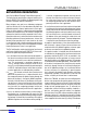
A graphical representation of the aforementioned ther
-
mal resistances
is given in Figure 8; blue resistances are
contained within the μModule regulator, whereas green
resistances are external to the µModule package.
As a practical matter, it should be clear to the reader that
no individual or sub-group of the four thermal resistance
parameters defined by JESD 51-12 or provided in the
Pin Configuration section replicates or conveys normal
operating conditions of a μModule regulator. For example,
in normal board-mounted applications, never does 100%
of the device’s total power loss (heat) thermally conduct
exclusively through the top or exclusively through bot
-
tom of
the µModule package—as the standard defines
for θ
JCtop
and θ
JCbottom
, respectively. In practice, power
loss is thermally dissipated in both directions away from
the package—granted, in the absence of a heat sink and
airflow, a majority of the heat flow is into the board.
Within the LTM4644, be aware there are multiple power
devices and components dissipating power, with a con
-
sequence that the thermal resistances relative to different
junctions of components or die are not exactly linear with
respect to total package power loss. To reconcile this
complication without sacrificing modeling simplicity—
but also, not ignoring practical realities—an approach
has been taken using FEA software modeling along with
laboratory testing in a controlled-environment chamber
to reasonably define and correlate the thermal resistance
values supplied in this data sheet: (1) Initially, FEA software
Downloaded from Arrow.com.Downloaded from Arrow.com.Downloaded from Arrow.com.Downloaded from Arrow.com.Downloaded from Arrow.com.Downloaded from Arrow.com.Downloaded from Arrow.com.Downloaded from Arrow.com.Downloaded from Arrow.com.Downloaded from Arrow.com.Downloaded from Arrow.com.Downloaded from Arrow.com.Downloaded from Arrow.com.Downloaded from Arrow.com.Downloaded from Arrow.com.Downloaded from Arrow.com.Downloaded from Arrow.com.