
Datasheet


LTM4644/LTM4644-1
9
Rev. F
For more information www.analog.com
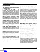
SYMBOL PARAMETER CONDITIONS MIN TYP MAX UNITS
C
IN
External Input Capacitor Requirement
(V
IN
= 4V to 14V, V
OUT
= 1.5V)
I
OUT
= 4A 4.7 10 µF
C
OUT
External Output Capacitor Requirement
(V
IN
= 4V to 14V, V
OUT
= 1.5V)
I
OUT
= 4A 22 47 µF
DECOUPLING REQUIREMENTS
OPERATION
The LTM4644 is a quad output standalone non-isolated
switch mode DC/DC power supply. It has four separate
regulator channels with each of them capable of delivering
up to 4A continuous output current with few external input
and output capacitors. Each regulator provides precisely
regulated output voltage programmable from 0.6V to 5.5V
via a single external resistor (two resistors for LTM4644-1)
over 4V to 14V input voltage range. With an external bias
voltage, this module can operate from an input voltage
as low as 2.375V. The typical application schematic is
shown in Figure 33.
The LTM4644 integrates four separate constant frequency
controlled on-time valley current mode regulators, power
MOSFETs, inductors, and other supporting discrete com
-
ponents. The
typical switching frequency is set to 1MHz.
For switching noise-sensitive applications, the µModule
regulator can be externally synchronized to a clock from
700kHz to 1.3MHz. See the Applications Information
section.
With current mode control and internal feedback loop
compensation, the LTM4644 module has sufficient stabil
-
ity margins
and good transient performance with a wide
range of output capacitors, even with all ceramic output
capacitors.
Current mode control provides the flexibility of paralleling
any of the separate regulator channels
with accurate
cur-
rent sharing. With a built-in clock interleaving between
each two regulator channels, the LTM4644 could easily
employ a 2+2, 3+1 or 4 channels parallel operation which
is more than flexible in a multirail POL application like
FPGA. Furthermore, the LTM4644 has CLKIN and CLK
-
OUT pins
for frequency synchronization or polyphasing
multiple devices which allow up to 8 phases cascaded to
run simultaneously.
Current mode control also provides cycle-by-cycle fast
current monitoring. Foldback current limiting is provided
in an overcurrent condition to reduce the inductor valley
current to approximately 40% of the original value when
V
FB
drops. An internal overvoltage and undervoltage
comparators pull the open-drain PGOOD output low if
the output feedback voltage exits a ±10% window around
the regulation point. Continuous conduction mode (CCM)
operation is forced during OV and UV conditions except
during start-up when the TRACK pin is ramping up to 0.6V.
Pulling the RUN pin below 1.1V forces the controller into
its shutdown state, turning off both power MOSFETs and
most of the internal control circuitry. At light load cur
-
rents, discontinuous conduction mode (DCM) operation
can be enabled to achieve higher efficiency compared to
continuous conduction mode (CCM) by setting the
MODE
pin to SGND. The TRACK/SS pin is used for power supply
tracking and soft-start programming. See the Applications
Information section.
A temperature diode is included inside the module to moni
-
tor the
temperature of the module. See the Applications
Information section for details.
(per Channel)
Downloaded from Arrow.com.Downloaded from Arrow.com.Downloaded from Arrow.com.Downloaded from Arrow.com.Downloaded from Arrow.com.Downloaded from Arrow.com.Downloaded from Arrow.com.Downloaded from Arrow.com.Downloaded from Arrow.com.