
Datasheet


LTM8021
7
8021fc
OPERATION
APPLICATIONS INFORMATION
For most applications, the design process is straight
forward, summarized as follows:
1. Refer to Table 1 for the row that has the desired input
range and output voltage.
2. Apply the recommended C
IN
, C
OUT
and R
ADJ
values.
3. Connect BIAS as indicated.
While these component combinations have been tested for
proper operation, it is incumbent upon the user to verify
proper operation over the intended system’s line, load and
environmental conditions.
If the desired output voltage is not listed in Table 1, set the
output by applying an R
ADJ
resistor whose value is given
by the equation, R
ADJ
= 80/(V
OUT
– 0.80), where R
ADJ
is
in k and V
OUT
is in volts. Verify the LTM8021’s operation
over the system’s intended line, load and environmental
conditions.
Minimum Duty Cycle
The LTM8021 has a fi xed 1.1MHz switching frequency. For
any given output voltage, the duty cycle falls as the input
voltage rises. At very large V
IN
to V
OUT
ratios, the duty
cycle can be very small. Because the LTM8021’s internal
controller IC has a minimum on-time, the regulator will
skip cycles in order to maintain output voltage regulation.
This will result in a larger output voltage ripple and pos-
sible disturbances during recovery from a transient load
step. The component values provided in Table 1 allow for
skip cycle operation, but hold the resultant output ripple
to around 50mV, or less. If even less ripple is desired,
then more output capacitance may be necessary. Adding
a feedforward capacitor has been empirically shown to
modestly extend the input voltage range to where the
LTM8021 does not skip cycles. Apply the feedforward
capacitor between the V
OUT
pins and ADJ. This injects
perturbations into the control loop, therefore, values
larger than 50pF are not recommended. A good value to
start with is 12pF.
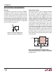
The LTM8021 is a standalone nonisolated step-down
switching DC/DC power supply. It can deliver up to
500mA of DC output current with only bulk external input
and output capacitors. This module provides a precisely
regulated output voltage programmable via one external
resistor from 0.8V
DC
to 5V
DC
. The input voltage range is 3V
to 36V. Given that the LTM8021 is a step-down converter,
make sure that the input voltage is high enough to support
the desired output voltage and load current. Please refer
to the simplifi ed Block Diagram.
The LTM8021 contains a current mode controller, power
switching element, power inductor, power Schottky diode
and a modest amount of input and output capacitance.
With its high performance current mode controller and
internal feedback loop compensation, the LTM8021 module
has suffi cient stability margin and good transient perfor-
mance under a wide range of operating conditions with a
wide range of output capacitors, even all ceramic ones (X5R
or X7R). Current mode control provides cycle-by-cycle fast
current limit, and automatic current limiting protects the
module in the event of a short circuit or overload fault.
The LTM8021 is based upon a 1.1MHz fi xed frequency
PWM current mode controller, equipped with cycle skip
capability for low voltage outputs or light loads. A fre-
quency foldback scheme helps to protect internal com-
ponents from overstress under heavy and short-circuit
output loads.
The drive circuit for the internal power switching element
is powered through the BIAS pin. Power this pin with at
least 3V.