
Datasheet


LTM8023
11
8023fj
For more information www.linear.com/LTM8023
APPLICATIONS INFORMATION
Ceramic capacitors are also piezoelectric. In Burst Mode
operation, the LTM8023’s switching frequency depends
on the load current, and can excite a ceramic capacitor
at audio frequencies, generating audible noise. Since the
LTM8023 operates at a lower current limit during Burst
Mode operation, the noise is typically very quiet to a
casual ear.
If this audible noise is unacceptable, use a high performance
electrolytic capacitor at the output. The input capacitor can
be a parallel combination of a 2.2µF ceramic capacitor and
a low cost electrolytic capacitor.
A final precaution regarding ceramic capacitors concerns
the maximum input voltage rating of the LTM8023. A
ceramic input capacitor combined with trace or cable
inductance forms a high Q (under damped) tank circuit.
If the LTM8023 circuit is plugged into a live supply, the
input voltage can ring to twice its nominal value, possi-
bly exceeding the device’s rating. This situation is easily
avoided; see the Hot-Plugging Safely section.
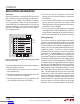
Frequency Selection
The LTM8023 uses a constant frequency PWM architecture
that can be programmed to switch from 200kHz to 2.4MHz
by using a resistor tied from the R
T
pin to ground. Table 2
provides a list of R
T
resistor values and their resultant
frequencies.
Table 2. Switching Frequency vs R
T
Value
SWITCHING FREQUENCY (MHz) R
T
VALUE (kΩ)
0.2
0.3
0.4
0.5
0.6
0.7
0.8
0.9
1.0
1.2
1.4
1.6
1.8
2.0
2.2
2.4
187
124
88.7
69.8
56.2
46.4
39.2
34.6
29.4
23.7
19.6
15.8
13.3
11.5
9.76
8.66
Operating Frequency Trade-Offs
It is recommended that the user apply the optimal R
T
value given in Table 1 for the input and output operating
condition. System level or other considerations, however,
may necessitate another operating frequency. While the
LTM8023 is flexible enough to accommodate a wide range
of operating frequencies, a haphazardly chosen one may
result in undesirable operation under certain operating or
fault conditions. A frequency that is too high can reduce
efficiency, generate excessive heat or even damage the
LTM8023 if the output is overloaded or short circuited. A
frequency that is too low can result in a final design that has
too much output ripple or too large of an output capacitor.
The maximum frequency (and attendant R
T
value) at which
the LTM8023 should be allowed to switch is given in Table
1
in the f
(MAX)
column, while the recommended frequency
(and R
T
value) for optimal efficiency over the given input
condition is given in the f
OPTIMAL
column.
There are additional conditions that must be satisfied if
the synchronization function is used. Please refer to the
Synchronization section for details.
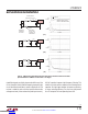
BIAS Pin Considerations
The BIAS pin is used to provide drive power for the internal
power switching stage and operate internal circuitry. For
proper operation, it must be powered by at least 2.8V. If
the output voltage is programmed to be 2.8V or higher,
simply tie BIAS to V
OUT
. If V
OUT
is less than 2.8V, BIAS
can be tied to V
IN
or some other voltage source. In all
cases, ensure that the maximum voltage at the BIAS pin
is both less than 16V and the sum of V
IN
and BIAS is less
than 56V. If BIAS power is applied from a remote or noisy
voltage source, it may be necessary to apply a decoupling
capacitor locally to the LTM8023.
Downloaded from Arrow.com.Downloaded from Arrow.com.Downloaded from Arrow.com.Downloaded from Arrow.com.Downloaded from Arrow.com.Downloaded from Arrow.com.Downloaded from Arrow.com.Downloaded from Arrow.com.Downloaded from Arrow.com.Downloaded from Arrow.com.Downloaded from Arrow.com.