PRINTER’S INSTRUCTIONS: INSTR,INSTL,AK-21 - LINEAR P/N: 228045 A - INK: BLACK - MATERIAL: 20 LB. MEAD BOND - SIZE: 8.500” X 11.000” - SCALE: 1-1 - FOLDING: ALBUM-FOLD - BINDING: SADDLE-STITCH AK-21 Digital Keyless Entry System Installation and Programming Instructions (760) 438-7000 USA & Canada (800) 421-1587 & (800) 392-0123 Toll Free FAX (800) 468-1340 www.linearcorp.
CONTENTS COMPONENT LOCATIONS . . . . . . . . . . . . . . . . . . . . . . . . . . . . . . . . . . . . . . . WIRING DIAGRAM. . . . . . . . . . . . . . . . . . . . . . . . . . . . . . . . . . . . . . . . . . . . INSTALLATION . . . . . . . . . . . . . . . . . . . . . . . . . . . . . . . . . . . . . . . . . . . . . . . Opening the Keypad . . . . . . . . . . . . . . . . . . . . . . . . . . . . . . . . . . . . . . . Changing the Keypad’s Bezel . . . . . . . . . . . . . . . . . . . . . . . . . . . . . . . . .
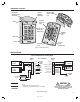
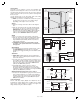
COMPONENT LOCATIONS RED/GREEN POWER/ACCESS INDICATOR MASTER CODE RESET JUMPER (JP2) YELLOW "LOCKOUT" INDICATOR TERMINAL BLOCK #2 (TB2) BEZEL SOLID STATE WHITE LED DOWN LIGHT TERMINAL BLOCK #1 (TB1) FACEPLATE KEYPAD BEEPER LEVEL JUMPER (JP1) MOUNTING PLATE Figure 1. Component Locations WIRING DIAGRAM TYPICAL DOOR INSTALLATION WIRING AK-21 TERMINALS TERMINAL BLOCK 2 1 - AC OR DC POWER SUPPLY 2 - AC OR DC 12-24 VOLT AC OR DC POWER 3 - N.O. MAIN RELAY 4 - COM 5 AMPS @ 28 VDC MAX. 5 - N.C.
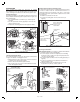
INSTALLATION Before installing the keypad, the unit must be partially disassembled to access the mounting plate. The keypad’s bezel can be exchanged for a different color when the keypad is apart. Opening the Keypad The keypad assembly is secured with two tamper-resistant screws that are hidden behind the keypad’s faceplate. Refer to Figure 3 for disassembly details. ❑ Use a small flat blade screwdriver to pry off the keypad’s faceplate.
Keypad Wiring See Figure 7 for an example of a basic door installation. The keypad is mounted adjacent to the door. An electric door strike is mounted in the door jamb to release the door lock. A magnetic switch is mounted on the top of the door jamb for detecting when the door is open. Use the following steps to wire the keypad. Refer to the wiring diagram shown in Figure 8 to assist in the wiring. ☞ NOTE: Up to 500 feet of 18 AWG wire can be run for power, use larger wire for longer runs.
FACTORY DEFAULTS Adding a New Entry Code MASTER PROGRAMMING CODE . . . . . . . . . . . . . . . . . . . . . . . . . . . . . . . . . . . . . . .123456 ENTRY CODE LENGTH . . . . . . . . . . . . . . . . . . . . . . . . . . . . . . . . . . . . . . . . . . . . . 4 DIGITS REQUEST-TO-EXIT OUTPUT RELAY . . . . . . . . . . . . . . . . . . . . . . . . . . . . . . . . . .MAIN RELAY ALARM SHUNT OUTPUT . . . . . . . . . . . . . . . . . . . . . . . . . . . . . . . . . . . . . . . . . . DISABLED FORCED ENTRY OUTPUT . . .
PROGRAMMING OPTIONS There are several AK-21 programming options. For most installations, the factory set default options are sufficient. The keypad must be in Programming Mode to make these changes. Select Request-to-Exit Output Default: Main Relay Sets which output activates when the Request-to-Exit input is grounded. This output may be timed or toggled.
Beep Sounds During Auxiliary Relay Default: No Selects whether or not the keypad beeps during Auxiliary Relay activation. Press: 4 2 # Sound # Sound = 1 for Yes, = 0 for No Beep Sounds During Output #3 Default: No Selects whether or not the keypad beeps during Output #3 activation. Press: 4 3 # Sound # Sound = 1 for Yes, = 0 for No Beep Sounds During Output #4 Default: No Selects whether or not the keypad beeps during Output #4 activation.