PRINTER’S INSTRUCTIONS: INSTR,INSTL,AK-31 - LINEAR P/N: 228037 A - INK: BLACK - MATERIAL: 20 LB. MEAD BOND - SIZE: 8.500” X 11.000” - SCALE: 1-1 - FOLDING: ALBUM-FOLD - BINDING: SADDLE-STITCH AK-31 Digital Keyless Entry System 1 2 3 4 5 6 7 8 9 0 Installation and Programming Instructions (760) 438-7000 USA & Canada (800) 421-1587 & (800) 392-0123 Toll Free FAX (800) 468-1340 www.linearcorp.
CONTENTS COMPONENT LOCATIONS . . . . . . . . . . . . . . . . . . . . . . . . . . . . . . . . . . . . . . . WIRING DIAGRAM. . . . . . . . . . . . . . . . . . . . . . . . . . . . . . . . . . . . . . . . . . . . INSTALLATION . . . . . . . . . . . . . . . . . . . . . . . . . . . . . . . . . . . . . . . . . . . . . . . Opening the Keypad . . . . . . . . . . . . . . . . . . . . . . . . . . . . . . . . . . . . . . . Install the Electrical Box and Mounting Plate . . . . . . . . . . . . . . . . . . . . . .
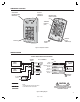
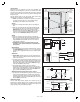
COMPONENT LOCATIONS RED/GREEN POWER/ACCESS INDICATOR YELLOW "LOCKOUT" INDICATOR MASTER CODE RESET JUMPER (P5) TERMINAL BLOCK #1 (TB1) 1 2 3 4 5 6 7 8 9 0 KEYPAD BEEPER LEVEL JUMPER (P4) MOUNTING PLATE Figure 1. Component Locations WIRING DIAGRAM TYPICAL DOOR INSTALLATION WIRING AK-31 TERMINALS TERMINAL BLOCK 1 1 - AC OR DC POWER SUPPLY 2 - AC OR DC 12-24 VOLT AC OR DC POWER 3 - N.O. MAIN RELAY 4 - COM 5 AMPS @ 28 VDC MAX. 5 - N.C. ELECTRIC DOOR STRIKE 6 - N.O.
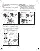
INSTALLATION Before installing the keypad, the unit must be partially disassembled to access the mounting plate. Opening the Keypad The keypad assembly is secured with two screws that are hidden behind the keypad’s nameplate. Refer to Figure 3 for disassembly details. ❑ Use a small flat blade screwdriver to pry off the keypad’s nameplate. ❑ Use a philips head screwdriver to remove the two screws. ❑ Separate the mounting plate from the keypad assembly.
Keypad Wiring See Figure 6 for an example of a basic door installation. The keypad is mounted adjacent to the door. An electric door strike is mounted in the door jamb to release the door lock. A magnetic switch is mounted on the top of the door jamb for detecting when the door is open. Use the following steps to wire the keypad. Refer to the wiring diagram shown in Figure 7 to assist in the wiring. ☞ NOTE: Up to 500 feet of 18 AWG wire can be run for power, use larger wire for longer runs.
FACTORY DEFAULTS Adding a New Entry Code MASTER PROGRAMMING CODE . . . . . . . . . . . . . . . . . . . . . . . . . . . . . . . . . . . . . . .123456 ENTRY CODE LENGTH . . . . . . . . . . . . . . . . . . . . . . . . . . . . . . . . . . . . . . . . . . . . . 4 DIGITS REQUEST-TO-EXIT OUTPUT RELAY . . . . . . . . . . . . . . . . . . . . . . . . . . . . . . . . . .MAIN RELAY ALARM SHUNT OUTPUT . . . . . . . . . . . . . . . . . . . . . . . . . . . . . . . . . . . . . . . . . . DISABLED FORCED ENTRY OUTPUT . . .
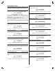
PROGRAMMING OPTIONS There are several AK-31 programming options. For most installations, the factory set default options are sufficient. The keypad must be in Programming Mode to make these changes. Select Door Sense or Inhibit Input Default: Door Sense The input (gray wire) can be programmed for DOOR SENSE or INHIBIT. Press: 1 0 # Input # Select Request-to-Exit Output Default: Main Relay Sets which output activates when the Request-to-Exit input is grounded. This output may be timed or toggled.
Keypad Lockout Count Default: 3 Tries Sets the number of incorrect entry code attempts allowed before the keypad “locks out”. Press: 5 0 # Attempts # Attempts = Number of attempts before lockout (2-7) Anti-passback Time Default: No Anti-passback Sets the length of time an entry code will not function after it is used.