PRINTER’S INSTRUCTIONS: INSTR,INSTL,AKR-1 - LINEAR P/N: 217350 D - INK: BLACK - MATERIAL: 20 LB. MEAD BOND - SIZE: 7.000” X 4.750” - SCALE: 1-1 - FOLDING: ALBUM-FOLD - BINDING: SADDLE-STITCH AKR-1 Digital Keyless Entry System With Built-in Wireless Receiver Installation and Programming Instructions (760) 438-7000 • FAX (760) 438-7043 USA & Canada (800) 421-1587 & (800) 392-0123 Toll Free FAX (800) 468-1340 www.linearcorp.
CONTENTS FEATURES . . . . . . . . . . . . . . . . . . . . . . . . . . . . . . . . . . . . . . . . . . . 1 INSTALLATION . . . . . . . . . . . . . . . . . . . . . . . . . . . . . . . . . . . . . . . . 1 COMPONENT LOCATIONS . . . . . . . . . . . . . . . . . . . . . . . . . . . . . . . . 2 WIRING DIAGRAM . . . . . . . . . . . . . . . . . . . . . . . . . . . . . . . . . . . . 3 FACTORY DEFAULTS . . . . . . . . . . . . . . . . . . . . . . . . . . . . . . . . . . . . 7 BASIC PROGRAMMING . . . . . . . . . . . . . .
FEATURES ✓ ✓ ✓ ✓ ✓ ✓ ✓ ✓ ✓ ✓ ✓ ✓ ✓ ✓ ✓ ✓ ✓ ✓ ✓ ✓ ✓ INSTALLATION KEYPAD PROGRAMMABLE 480 ENTRY CODE CAPACITY 480 TRANSMITTER CAPACITY SUPPORTS 4 BLOCKS OF TRANSMITTERS WITH 4 FACILITY CODES WEATHER-PROOF, TAMPER-RESISTANT RADIO ANTENNA SUPPORTS 1 MODEL MGT SAFETY EDGE TRANSMITTER 1-6 DIGIT ENTRY CODE LENGTH 4 INDEPENDENT OUTPUTS (TIMED/TOGGLED) 4 INDEPENDENT TIMERS EACH ENTRY CODE CAN BE PROGRAMMED TO ACTIVATE EITHER OR BOTH RELAYS RELAY CONTACTS ARE FORM “C” (N.O. & N.
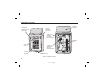
COMPONENT LOCATIONS RED/GREEN POWER/ACCESS INDICATOR ANTENNA (HIDDEN) YELLOW "LOCKOUT" INDICATOR JUMPER JP2 REMOVE TO RESET MASTER CODE TERMINAL BLOCK NIGHT LIGHT TACTILE KEYPAD JUMPER JP1 REMOVE TO REDUCE BEEPER SOUND KEYLOCK Figure 1.
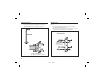
WIRING DIAGRAM TYPICAL GATE INSTALLATION WIRING TYPICAL DOOR INSTALLATION WIRING AKR-1 TERMINALS MAIN RELAY N.O. 1 COMMON 2 AKR-1 TERMINALS OPEN N.C. 3 OUTPUT #3 4 OUTPUT #4 5 GATE OPERATOR TRANSFORMER ISOLATED AUXILIARY POWER 6 DC OR AC POWER AUXILIARY RELAY MAIN RELAY 7 N.O. 1 COMMON 2 N.C. 3 OUTPUT #3 4 OUTPUT #4 5 6 DC OR AC POWER 8 COMMON 8 N.O. 9 N.O. 9 AUXILIARY RELAY COMMON 10 FIRE ACCESS COMMON 10 COMMON 13 INHIBIT 14 EARTH GROUND 15 NOTES: 1.
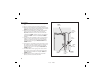
Pedestal Mounting Wall Mounting The AKR-1 keypad can be mounted on a standard pedestal. ❑ Use four security bolts and locking nuts to secure the keypad’s backplate to the pedestal (see Figure 3). The AKR-1 keypad can be mounted directly to a wall or flat surface. ❑ Use the appropriate fasteners to secure the keypad’s backplate to the mounting surface. ❑ When mounting the keypad to a concrete wall, use concrete wedge anchors or molly anchors (see Figure 4).
Gate Control Refer to Figure 5 for an outline of a typical gate installation. ❑ Route four wires between the gate and the keypad (two for power, two for control). ❑ Connect the gate operator’s auxiliary or radio power output terminals to the keypads POWER input terminals (observe wiring polarity). ❑ Connect the gate operator’s OPEN terminals to the keypad’s Relay #1 COMMON & N.O. terminals. ☞ NOTE: For operator wiring specifics, refer to the gate operator’s wiring diagram.
Door Control ❑ Install a low voltage electric door strike for unlocking the door. ❑ Choose a location for the power supply or transformer. ❑ Route two wires between the power supply and the keypad. Connect the power supply’s output terminals to the keypad’s POWER input terminals (observe wiring polarity). ❑ Route two wires between the door strike and the keypad. Connect one of the door strike wires to the keypad’s Relay #1 N.O. terminal. Connect the other door strike wire to the keypad’s POWER + terminal.
FACTORY DEFAULTS BASIC PROGRAMMING MASTER PROGRAMMING CODE . . . . . . . . . . . . . . . . . . . . . . . . . . . . . . . . . . . . . . . 123456 ENTRY CODE LENGTH . . . . . . . . . . . . . . . . . . . . . . . . . . . . . . . . . . . . . . . . . . . . . 4 DIGITS REQUEST-TO-ENTER OUTPUT . . . . . . . . . . . . . . . . . . . . . . . . . . . . . . . . . . . . . . . . RELAY #1 ALARM SHUNT OUTPUT . . . . . . . . . . . . . . . . . . . . . . . . . . . . . . . . . . . . . . . . . . DISABLED FORCED ENTRY OUTPUT . .
Adding a New Entry Code Press: 0 1 # Code # Code # Relay # Code = The new entry code: 1-999999, depending on code length Relay = Relay output entry code will activate: 1 = Relay #1 2 = Relay #2 3 = Both Relays The yellow indicator will flash quickly while the AKR-1 searches its memory for available space and duplicate entries. The green indicator will light when the new code is stored. If the new entry code chosen is already being used for another entry code, the red indicator will light.
Typical Toggle Mode Wiring For devices triggered by a normally open circuit, wire the contacts of the Main and Auxiliary Relays in parallel (see the Figure below). Either relay will be able to trigger the access device. Entry codes programmed for the Auxiliary Relay will be able to hold the output on. N.O. MAIN RELAY AKR-1 OUTPUTS AUXILIARY RELAY COMMON Select Forced Entry Output Default: Output #3 Sets which output activates if the DOOR SENSE input opens before access is granted.
Press: 2 4 # Seconds # Select Alarm Shunt Output Default: No Output Sets which output activates during the time access is granted. (Use this output to shunt alarm contacts attached to the access door.) This output may be timed or toggled. Beep Sounds on Keystrokes Default: Yes Selects whether or not the keypad beeps as each key is pressed.
Anti-passback Time Default: No Anti-passback Sets the length of time an entry code or transmitter will not function after it is used. Press: 9 0 # TX ID # Status # Press: 5 1 # Minutes # Selecting the Facility Codes Default: Ignore Facility Code Facility Codes increase security by requiring the Facility Code as well the TX ID code to match before access is granted. Up to four Facility Codes can be entered. The Facility Code number is labeled on the box of block coded transmitters.
BOTH FUNCTION AS LEFT BUTTON LEFT BUTTON Select Right Button Output Default: Relay #2 Sets which relay output activates when a transmitter’s right button is pressed. This setting effects all transmitters used with the AKR-1. See Figure 7 for transmitter button designations for various models.
Master Reset ✦ CAUTION: Performing a master reset will clear the entire memory of the AKR-1 and return all programmable options to the factory default values. ALL ENTRY CODES AND TRANSMITTERS WILL BE ERASED. STEP 1 Disconnect power from the keypad. STEP 2 Press and hold down the * and # keys. STEP 3 Apply power to the keypad, continue holding the keys down until the red indicator starts flashing. STEP 4 Release the keys.
Beeper Sound Level Locking Keypad The keypad’s beeper can be set to low or high level. ❑ If the keypad’s beeper is too loud for the keypad’s location, remove jumper JP1 (see Figure 9). After the installation is complete. Lock the keypad using the keylock (see Figure 10). REMOVE JUMPER JP1 TO REDUCE THE BEEPER VOLUME HOOK KEYPAD ONTO BACKPLATE USE KEY TO LOCK KEYPAD Figure 10. Locking the Keypad Case Figure 9.
AKR-1 OPERATION With Entry Code ❑ Users of the AKR-1 have up to 40 seconds to key in their entry code. ❑ Up to eight seconds are allowed between each keystroke. ❑ All digits of the entry code must be entered. Example: If the code is 0042, the user must enter “0 0 4 2”. ❑ If the wrong key is pressed, pressing the key will reset the * keypad. The correct code can then be re-entered.
MGT OBSTACLE TRANSMITTER OPERATION RADIO TEST MODE One Model MGT obstacle transmitter can be programmed into the AKR-1. The MGT is triggered with a safety edge contact and will activate the AKR-1 Relay #2 for the programmed length of time. A special mode is provided to test transmitters and determine if there is radio frequency interference present. The keypad will function normally while it is in Radio Test Mode.
SPECIFICATIONS MECHANICAL Case dimensions: ELECTRICAL Voltage: Current: Outputs: LINEAR LIMITED WARRANTY This Linear product is warranted against defects in material and workmanship for twelve (12) months. The Warranty Expiration Date is labeled on the product. This warranty extends only to wholesale customers who buy direct from Linear or through Linear’s normal distribution channels. Linear does not warrant this product to consumers.
IMPORTANT !!! FCC NOTICE Linear radio controls provide a reliable communications link and fill an important need in portable wireless signaling. However, there are some limitations which must be observed. • For U.S. installations only: The radios are required to comply with FCC Rules and Regulations as Part 15 devices. As such, they have limited transmitter power and therefore limited range.