Boiler Manual And Installation Instructions for Atmospheric Venting LINEAR 6-12 SECTION BIASI B/40 PAGE 1 Please Read Instructions Carefully Save for Future Reference WARNING If the information in this manual is not followed exactly, a fire explosion may result causing property damage, personal injury or loss of life.
PAGE 2 BIASI B/40 Dear Customer: Thank you for buying a Linear commercial boiler. The Linear is a cast iron, oil or gas fired hot water boiler, using the famous 3-pass design. The boiler is simple, rugged and engineered for maximum heating efficiency. We realize that it is not possible to answer all questions about the Linear series boiler in this manual.
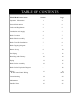
PAGE 3 BIASI B/40 TABLE OF CONTENTS BIASI B-40 Linear Series Section Page Important Information 1 4 General Information 2 6 Codes and Regulations 3 6 Combustion Air Supply 4 7 Boiler Location 5 7 Boiler Block Assembly 6 8 Boiler Trim Kit Installation 7 8 Boiler Tapping Diagram - 9 Burner Set-up 8 10 Gas Piping 9 12 Breeching and Chimney 10 14 Piping 11 15 Boiler Jacket Assembly 12 17 Boiler Jacket Explosion Diagram - 18 Wiring B-40 Control Panel Wiring 13 19
BIASI B/40 PAGE 4 IMPORTANT INFORMATION Please read this page carefully. ALL BOILERS MUST BE INSTALLED IN ACCORDANCE WITH NATIONAL, STATE AND LOCAL PLUMBING, HEATING AND ELECTRICAL CODES AND ORDINANCES, AS WELL AS THE REGULATIONS OF THE SERVING ELECTRICAL, WATER AND GAS UTILITIES. All systems should be designed by competent contractors, and only persons knowledgeable in the layout and installation of heating systems should attempt the installation of any boiler.
PAGE 5 BIASI B/40 WARNING Any appliance that burns natural gas, propane gas, fuel oil, wood or coal is capable of producing carbon monoxide (CO). Carbon Monoxide (CO) is a gas which is odorless, colorless and tasteless but is very toxic. If your BIASI B-40 boiler is not working properly, or is not vented properly, dangerous levels of CO may accumulate. CO is lighter than air and thus may travel throughout the building.
BIASI B/40 PAGE 6 2. General Information: The Linear series are wet base design, sectional, cast-iron boilers for forced hot water heating systems. The Linear boilers are designed for firing with oil and deliver high efficiencies through unique design and construction. The Linear series boilers are shipped from the factory in assembled blocks and each boiler can range from 6 to 12 sections. The sections can then be disassembled before delivery to the jobsite by QHT and then field assembled.
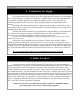
PAGE 7 BIASI B/40 4. Combustion Air Supply: The boiler location must provide air for proper combustion and ventilation of the surrounding area. To burn efficiently, oil requires 30 CFM/GAL. In general, boiler rooms should incorporate two (2) permanent air supply openings, one commencing within 12 inches of the ceiling, and one commencing within 12 inches of the floor. These openings should freely communicate with the outdoors.
BIASI B/40 PAGE 8 6. Boiler Block Assembly: All Linear series boilers are shipped either as an assembled boiler block or a knock-down boiler block. If the block came unassembled, or if the assembled block needs to be split for installation purposes, please read the following: To assemble split blocks, move the sections into a line facing each other. Sections may be slid along boards placed underneath the sections. Inspect nipple ports for damage or burrs.
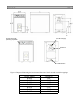
PAGE 9 BIASI B/40 Control Panel with operating aquastats 2.5” MPT Supply 8” Breech 2.5” MPT Return Figure 1:Diagram illustrating the location and function of the front and rear boiler tappings. Boiler Model B-40/6 B-40/7 B-40/8 B-40/9 B-4/10 B-4/11 B-4/12 Length (L) 34.8” 39.5” 44.5" 49.2" 53.9" 58.8" 63.
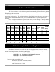
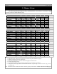
BIASI B/40 PAGE 10 8. Burner Setup: The following information applies only to the BIASI B-40 series boilers at a maximum output for power venters or lined chimneys only. BURNER MANUFACTURER Boiler Model B-406 P2-KA Burner Model 2.2 GPH Firing Rate FULL Insertion Depth 2.00 X 45 Nozzle solid Spray Pattern 140 psi Pump Pressure 12 Head Position 11.50 Air Setting B-407 P2-K 2.8 GPH FULL 2.25 X 60 solid 170 psi 16 15.00 B-408 P2-K 3.5 GPH FULL 2.75 X 60 solid 175 psi 18 18.
PAGE 11 BIASI B/40 8. Burner Setup: The following information applies only to the BIASI B-40 series boilers at a maximum output for power venters or lined chimneys only. BURNER MANUFACTURER Boiler Model B-406 SU-3 Burner Model Natural Fuel 315 Input 1" Min. Gas Inlet Size 1.95" Manifold in w.c. 9.5 Air 6 Head B-407 SU-3 Natural 420 1" 3" 14 11 B-408 SU-4 Natural 499 1" 3.5" 21 20 BURNER MANUFACTURER Boiler Model B-406 SU-3 Burner Model Propane Fuel 315 Input 3/4" Min. Gas Inlet Size 1.
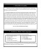
BIASI B/40 PAGE 12 9. Gas Line Piping Gas supply piping is to be sized and installed properly in order to provide a supply of gas sufficient to meet the maximum demand without undue loss of pressure between the meter and the boiler. It is advisable to run a separate gas line from the meter to the gas burner to avoid pressure drops. Consult with the National Fuel Gas Code ANSI Z223.1 for proper sizing of gas piping for various lengths and diameters.
BIASI B/40 PAGE 13 INSTALLATION OF SEDIMENT TRAP AND BURNER SUPPLY Piping should consist of: 1. A shut off valve approximately 6’ away from the unit. 2. A 1/8” plugged NPT tapping for gas pressure measurement preferably on the manual shut-off valve (as shown or anywhere between the gas valve and the shut off value). Note: The manual shut off valve and tapping are NOT part of the SU-4 Gas Burner. Please make sure you conform to local and state codes. 3. A gas union. 4. A drip pipe.
BIASI B/40 PAGE 14 10. Breeching and Venting: The B-40 Linear boiler is a high efficiency unit that requires proper venting. The boiler must be vented to the outdoors by means of a tile lined masonry or an approved pre-fabricated chimney of the size and height recommended by the manufacturer or by a listed "power venting" unit which provides draft by mechanical venting . The chimney discharge opening must be located at least 24 inches above any part of the building structure within 10 feet of the chimney.
PAGE 15 BIASI B/40 10. Blocked Flue Switch: 1. Pierce a 5/8” hole into the vent pipe near the appliance outlet. Remove one of the securing nuts from the pipe of the safety switch. Tighten the other securing nut onto the pipe as far as possible. 2. Insert the threaded pipe end into the pierced hole, then install the securing nut, then install the securing nut, which was removed in step 1, and tighten securely. 3. Please consult the wiring section of this manual for the wiring of the blocked flue switch.
PAGE 16 BIASI B/40
PAGE 17 BIASI B/40 12. Boiler Jacket Assembly: NOTE: All piping, boiler controls, gauges and valves must be installed before the jacket has been assembled on the boiler. Refer to the following page to clarify these boiler jacket assembly instructions. Insert the separate piece of insulation (# 92) on top of boiler so the entire top and sides of boiler are covered. Use plastic strapping to secure the insulation in place.
BIASI B/40 PAGE 18 13. Wiring: The electricity to the boiler shall come from a dedicated breaker in the electric service box. A service switch should be mounted on the side of the boiler so the burner man can service the burner and controls. The electrical wiring should be routed so as not to interfere with normal servicing of the boiler.
PAGE 19 BIASI B/40 CONTROL PANEL DESCRIPTION 1. 2. 3. 4. 5. 6. 7. 8. 9. On/Off Switch — Turns power to control panel on and off and will disable power to the burner assuming the panel is wired correctly. Minimum Boiler Temperature Thermostat — Maintains a minimum boiler temperature between 50 degrees F and 170 degrees F. Maximum Boiler Temperature Thermostat — High limit temperature setting for boiler between 50 degrees F and 205 degrees F.
BIASI B/40 PAGE 20 B-40 Control Panel Wiring Diagram for Beckett/Heat Wise Oil Burner 24V BURNER CONTROL CIRCULATOR RELAY
B-40 Control Panel Wiring Diagram for Beckett/Heat Wise Oil Burner Line Voltage BIASI B/40 PAGE 21 CIRCULATOR RELAY BURNER CONTROL
BIASI B/40 PAGE 22 B-40 Control Panel Wiring Diagram for Riello Oil Burner
B-40 Control Panel Wiring Diagram for Heat Wise Gas Burners BIASI B/40 PAGE 23 CIRCULATOR RELAY Burner Primary Control
BIASI B/40 PAGE 24 14. Commissioning: After installation of oil/gas-fired boiler, operation and performance tests shall be conducted to make certain that the burner is operating in an acceptable manner and that all safety controls and devices function properly. It is critical that the high limit, low water cutoff and burner "cad cell" relay be checked for normal operation before leaving the job. Refer to the back page of this manual to write down the System Checkout information. 15.
PAGE 25 BIASI B/40 16. Installer Notes System Checkout: Boiler Model No._________________ Serial No.__________ Original Purchaser: _________________________ Installer: ______________________ _________________________ ______________________ _________________________ ______________________ Burner Manufacturer----------- Type of Oil Burner------------- Burner Model No.-------------- Burner Serial No.-------------- Nozzle Manufacturer------------- Nozzle Spray Angle------------ G.P.H.
PAGE 26 BIASI B/40
BIASI B/40 PAGE 27
BIASI B/40 PAGE 28 Warranty For BIASI B40 Series Commercial Cast-Iron Water Boilers FIRST YEAR through TENTH YEAR-WARRANTY FOR B40 SERIES COMMERCIAL HOT WATER BOILERS: QHT warrants that its cast-iron boiler and casing are free from defects in material and workmanship for ten years from the date of installation at the original installation site to the original owner. If the boiler is found to be defective within this period, QHT will replace the boiler block or casing.