USA & Canada (800) 421-1587 & (800) 392-0123 (760) 438-7000 Toll Free FAX (800) 468-1340 www.linearcorp.com INSTALLATION AND OWNER’S MANUAL AUJ-S & AUH-S AU SERIES WITH SOLID STATE CONTROL CIRCUITRY JACKSHAFT COMMERCIAL VEHICULAR DOOR OPERATORS 107172 Serial #: Date Installed: As of date of manufacture, meets all ANSI/UL 325 Safety Requirements for Vehicular door operators.
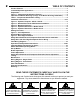
TABLE OF CONTENTS Product Features........................................................................................................... 3 Jackshaft Operator Applications ................................................................................. 3 Preparation .................................................................................................................... 4 Figure 1 - Component Identification Pictorial .............................................................
PRODUCT FEATURES Momentary Contact To Close: Standard operating mode. The purpose of this booklet is to provide assembly, installation and operation information concerning Model AUJ-S & AUH-S Commercial Vehicular Garage Door Operators and related Accessory Products. NOTICE IT IS IMPORTANT THAT THIS INSTRUCTION MANUAL BE READ AND UNDERSTOOD COMPLETELY BEFORE INSTALLATION OR OPERATION IS ATTEMPTED.
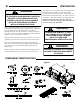
PREPARATION WARNING ELECTRIC DOOR OPENERS ARE DESIGNED FOR DOORS IN GOOD WORKING CONDITION, PROPERLY COUNTERBALANCED AND PROPERLY ADJUSTED IN ACCORDANCE WITH THE DOOR MANUFACTURER'S INSTALLATION INSTRUCTIONS. Before starting the installation of the operator, the door must be in good working condition and properly counterbalanced. Inspect the door and track for loose or missing hardware. Test the door manually for balance and ease of operation. Lubricate door hinges and rollers.
IMPORTANT INSTALLATION INSTRUCTIONS! WARNING 5 TO REDUCE THE RISK OF SEVERE INJURY OR DEATH: READ AND FOLLOW ALL INSTALLATION INSTRUCTIONS! • Install only on a properly operating and balanced garage door. A door that is operating improperly could cause severe injury. Have qualified service personnel make repairs to cables, spring assemblies and other hardware before installing the opener.
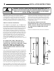
WARNING INSTALLATION INSTRUCTIONS SPRINGS, PULLEYS, CABLES AND MOUNTING HARDWARE USED TO BALANCE YOUR GARAGE DOOR ARE UNDER EXTREME TENSION AT ALL TIMES AND CAN CAUSE SEVERE INJURY OR DEATH IF DISTURBED. DO NOT ATTEMPT ADJUSTMENT. Figure 4, page 8 illustrates several positions suitable for mounting the operator; right hand or left hand, either wall mount or ceiling mount and center mount with direct coupling to the torsion shaft. Direct coupling may also be used in a side mount installation.
INSTALLATION INSTRUCTIONS DIRECT COUPLING MOUNTING CHAIN HOIST AND FLOOR DISCONNECT INSTALLATION Figure 4, page 8 illustrates several positions suitable for mounting the operator including center mount with direct coupling to the torsion shaft. Direct coupling may also be used in a side mount installation. Operators intended for direct coupling require an internal speed modification and must be ordered from the factory.
FIGURE 4 - OPERATOR MOUNTING POSITIONS Left Side Mount Ceiling Mount Center Mount Right Side Mount Direct Couple Ceiling Mount Wall Mount Wall Mount 100719 Figure 4
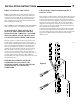
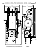
FIGURE 5 - OPERATOR DIMENSIONS - MODEL AUH-S 9 7.75 107173 NOTE: Dimensions for Model AUJ-S are similar to above, Model AUJ-S is not provided with a chain hoist.
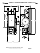
FIGURE 6 - OPERATOR DIMENSIONS - MODEL AUJ-S 15 7.75 107173 NOTE: Dimensions for Model AUH-S are similar to above, Model AUH-S is provided with a chain hoist.
INSTALLATION INSTRUCTIONS 4) Depress the limit nut retaining Plate (D) so it disengages from the slots in the limit nuts. Turn the OPEN limit nut (E) on the shaft until it engages the Open Limit Switch (A). You will need to listen for an audible click. Release the retaining plate and be sure that it engages in slots of both limit nuts. WARNING TO AVOID RISK OF ENTRAPMENT AND POSSIBLE DAMAGE TO THE DOOR AND OPERATOR THE LIMITS MUST BE ADJUSTED 5) Manually lower the door to approx.
INSTALLATION INSTRUCTIONS - ELECTRICAL WIRING WARNING TO PREVENT THE RISK OF PERSONAL INJURY OR DEATH : • DISCONNECT POWER AT THE FUSE BOX BEFORE PROCEEDING. • ELECTRICAL CONNECTIONS MUST BE MADE BY A QUALIFIED INDIVIDUAL. • OBSERVE LOCAL ELECTRICAL CODES WHEN WIRING THE OPERATOR. WARNING: The AUJ-S and AUH-S Series operators have been designed and constructed for use with voltages from 115 Volts AC to 480 Volts AC, in single or three phase.
DOOR EDGE and PHOTOELECTRIC INSTALLATION 13 Note: See the door edge manufacturer‟s installation instructions for the complete installation procedure. See Figure 9 for connecting the edge to the operator. See Page 17 for proper setting of the selector switches. These switches must be properly set and an approved photoelectric device or approved door edge device connected to the operator to obtain B2 Mode of Operation, Momentary Contact to Close.
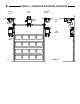
OPEN CLOSE STOP COM NO REV NC REV PHOTO COM SINGLE ILOCK 24 VAC COM 14 INSTALLATION INSTRUCTIONS ENTRAPMENT PROTECTION DEVICES WIRING INSTRUCTIONS Note A: Connect only one (1) approved entrapment protection device to terminals “Photo” and “Com”. If additional entrapment protection is desired connect additional photoelectric and door edges devices to “NC REV”, “NO REV” and “COM” terminals as shownSAFE here.
3/SINGLE BUTTON STATION / INTERLOCK FIELD WIRING D12 OPEN CLOSE C3 C11 C9 D8 R38 STOP R87 RADIO 24V COM RM3 RM2 RM1 VCC P7 R54 R30 PB3 MOTOR CONTROL BOARD R29 PB2 D2 C24 R26 PB1 C10 R57 R25 U4 C25 U1 R3 C1 R2 R65 PCB 112695 REV B TSLK R84 U5 R5 D3 MOTOR CONTROL BOARD R55 R56 C8 R94 R95 PB3 CLOSE STOP STOP CLOSE COM NC REV OPEN NO REV OPEN CLOSE STOP D12 COM NO REV NC REV PHOTO PB2 C1 C25 PB1 OPEN R3 PCB 112695 REV B TSLK R2 Figure 10 Single
OPERATION & ADJUSTMENT INSTRUCTIONS IMPORTANT SAFETY INSTRUCTIONS FOR OWNER WARNING TO REDUCE THE RISK OF SEVERE INJURY OR DEATH: READ AND FOLLOW ALL INSTRUCTIONS! Understand all of the operating features of your door control system at the time of its installation. Your installing dealer will demonstrate them for you. NEVER let children operate or play with door controls. Keep the Remote Control (where provided) away from children.
OPERATION & ADJUSTMENT INSTRUCTIONS SETTING THE SWITCH SELECTABLE OPERATING MODES B2 Operation (Factory Default) Open Button: Momentary activation; open override of closing door. Close Button: Momentary activation. Stop Button: Momentary activation; stops open, close or reverse action. Single Button: Momentary activation to open; open override of closing door, closes door from mid-stop or open limit.
OPERATION & ADJUSTMENT INSTRUCTIONS Mid-Stop: Activation stops an opening door; momentary contact of open button at mid stop will restart door to full open position; if door is moving open, constant pressure on open button will bypass mid-stop. Auto Close Timer: N/A TS Operation Open Button: Momentary activation; open override of closing door. Close Button: Momentary activation. Stop Button: Momentary activation; stops open, close or reverse action.
OPERATION & ADJUSTMENT INSTRUCTIONS Mid-Stop Limit Setup This features provides a timing function to stop a door as it is traveling open at a Mid Stop position instead of the full open position. The door can then be moved to the full open position if desired by pressing the Open button. A single button input when the door is at the mid stop position will cause the door to begin moving in the close direction. The factory default is not set; the minimum run time to mid-stop limit is 6 seconds.
OPERATION & ADJUSTMENT INSTRUCTIONS CLUTCH ADJUSTMENT WARNING RISK OF ENTRAPMENT THAT MAY RESULT IN SERIOUS PERSONAL INJURY OR DEATH. DISCONNECT POWER TO THE OPENER BEFORE SERVICING OR MAKING ADJUSTMENTS. ENSURE DOORWAY IS CLEAR BEFORE STARTING TESTING OF UNIT. CAUTION RUBBING AGAINST THE DOOR STOPS OR DEFECTIVE OR MISADJUSTED SPRINGS. ANY SERVICE REQUIRED TO THE DOOR, DOOR SPRINGS OR DOOR OPERATOR MUST BE PREFORMED BY A QUALIFIED PROFESSIONAL DOOR INSTALLER.
OPERATION & ADJUSTMENT INSTRUCTIONS 21
OPERATION & ADJUSTMENT INSTRUCTIONS TESTING Following installation, the operator MUST be tested and respond correctly to all controls as specified on the wiring diagram. KEEP personnel and equipment clear of the area beneath the door when performing the tests. When testing the 3 -button wall station, first observe that each button operates the door in the direction indicated and that the STOP button performs that function.
WIRING DIAGRAM/SCHEMATIC - SINGLE PHASE GREY GREY RUN START RED BRAKE 23 CLOSE LIMIT WHITE COM NO ORANGE ORANGE BLUE COM NO YELLOW OPEN LIMIT WHITE OVERLOAD DEVICE P4 BLACK L1 WHITE N K5 HIGH VOLTAGE K3 K4 K6 GROUND OPERATING MODES SWITCH SETTINGS MODE S1 S2 S3 S4 C2 OFF OFF OFF OFF B2 ON OFF OFF OFF D1 OFF ON OFF OFF E2 ON ON OFF OFF TS OFF OFF ON OFF T ON OFF ON OFF COM OLS TR3 MO4 CLS COM SW1 P1 S4 S3 S2 S1 POWE MO3 MO2 MO1 ILK P2 R89 TR1 24V P3 R49 R10 R62 R22 R47
WIRING DIAGRAM/SCHEMATIC - THREE PHASE CLOSE LIMIT WHITE GREY GREY BRAKE + RED COM NO ORANGE ORANGE BLUE COM NO +CONNECTION SHOWN FOR 208 & 230V - FOR 460V SEE MOTOR DIAG. ON INSIDE OF CONT.
PARTS IDENTIFICATION Ref Part# Description Parts Ref Part# Description Assemblies A C E G I 009020 Shaft Collar, 3/4” 2 008071 Flange Bearing, 3/4” 109351 Frame Assembly w/Shafts.
SPECIFICATIONS MODEL : AUJ_ _ _ _S VOLTS : _____ HP:_____ PHASE : _____ * UL AND CANADIAN UL LISTED * HIGH STARTING TORQUE, CONTINUOUS DUTY MOTOR * MOTOR OVERLOAD PROTECTION * CLASS 2 (24 VOLT) CONTROL CIRCUIT * SOLENOID BRAKE * SOLID STATE MOTOR CONTROL CIRCUITRY WITH ADVANCED OPERATIONAL FEATURES STANDARD * THREE BUTTON CONTROL: OPEN, CLOSE, STOP * WIRED TO ACCEPT REVERSING EDGE INPUT * HEAVY GAUGE, POWDER-COATED STEEL FRAME RAILS AND CONTROL BOX * ALL SPROCKETS AND PULLEYS PINNED OR KEYED, SOLID S