PRINTER’S INSTRUCTIONS: INSTR,INSTL,RE-1 - LINEAR P/N: 217490 C - INK: BLACK - MATERIAL: 20 LB. MEAD BOND WITH 80 LB. WHITE COATED COVER - SIZE: 8.500” X 11.000” - SCALE: 1-1 - FOLDING: ALBUM-FOLD - BINDING: SADDLE-STITCH RE-1 Residential Telephone Entry System With Built-in Wireless Receiver Installation, Programming, and Operation Instructions (760) 438-7000 USA & Canada (800) 421-1587 & (800) 392-0123 Toll Free FAX (800) 468-1340 www.linearcorp.
CONTENTS PRODUCT DESCRIPTION . . . . . . . . . . . . . . . . . . . . . . . . . .1 INSTALLATION INFORMATION . . . . . . . . . . . . . . . . . . . . 2 COMPONENT LOCATIONS . . . . . . . . . . . . . . . . . . . . . . . . 3 WIRING DIAGRAM. . . . . . . . . . . . . . . . . . . . . . . . . . . . . . 4 ENTRY SYSTEM MOUNTING . . . . . . . . . . . . . . . . . . . . . . 5 TELEPHONE WIRING . . . . . . . . . . . . . . . . . . . . . . . . . . . 5 TELEPHONE WIRING OPTIONS . . . . . . . . . . . . . . . . . . . .
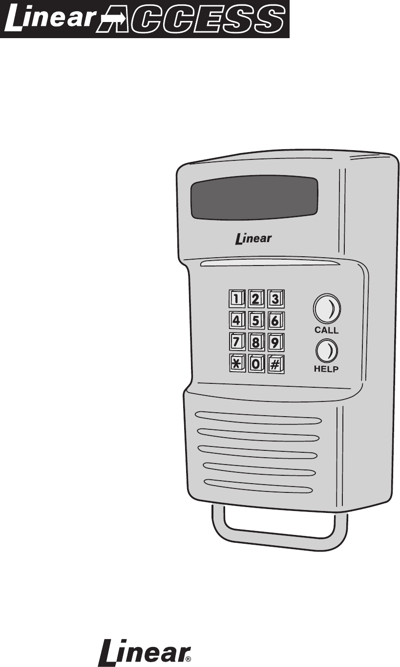
PRODUCT DESCRIPTION Linear’s RE-1 Telephone Entry System is designed for residential or light commercial access control applications. The speakerphone, keypad, radio receiver, and optional video camera are housed in a rugged enclosure that can be mounted to a pedestal or bolted directly to a wall. The die-cast keypad keys have bright, easy-toread graphics and are lit with an overhead light. The two operation buttons; CALL and HELP, are machined for heavy-duty reliability.
INSTALLATION INFORMATION Before beginning installation, please review the entire instructions and become familiar with the system’s operation, wiring, and programmable options. System Location For pedestrian door or gate installations, mount the Entry System on a rigid wall near the controlled door. Avoid mounting the unit in a location where regular mechanical shock will occur due to a slamming door or spring loaded pedestrian gate.
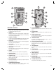
13 3 14 12 11 4 2 CALL 5 15 16 10 1 6 17 7 9 18 21 8 COMPONENT LOCATIONS 1 2 3 4 5 6 KEYPAD Die-cast metal 12-key keypad with tactile action. For system programming and keying in entry codes. DOWNLIGHT Illuminates keypad and visitor operation buttons. The light can be programmed to operate dusk to dawn and adjusts its time depending on the system’s geographic location. OPTIONAL CCTV CAMERA Location for the optional Model RE-BWC1 CCTV camera.
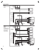
WIRING DIAGRAM RELAY #1 RELAY #2 N.C. COM N.O. N.C. N.O.
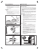
TELEPHONE WIRING ENTRY SYSTEM MOUNTING Pedestal Mounting The RE-1 Entry System can be mounted on a standard pedestal. 1. Open the RE-1 case by removing the two security screws with the wrench provided (see Figure 2). 2. Use four security bolts and locking nuts to secure the backplate to the pedestal (see Figure 3). Wall Mounting The RE-1 Entry System can be mounted directly to a wall or flat surface. 1. Open the RE-1 case by removing the two security screws with the wrench provided (see Figure 2). 2.
TELEPHONE WIRING OPTIONS Shared Line This is the standard configuration. The telephone line is routed through the RE-1 to the house phones. Pressing the Call button on the RE-1 will cause the RE-1 to disconnect the house phones from the telephone company line and generate a ring signal that is heard on the house phones. Intercom Mode Pressing the Call button on the RE-1 will cause the RE-1 to generate a ring signal as if it were an intercom station.
MULTIPLE UNIT INSTALLATIONS Any of the four basic operation modes (Shared Line, Dedicated Line, Intercom, and Ring Down) may be used with multiple RE-1s in the same installation. The telephone line wiring is “daisy chained” (the telephone line routes through one unit to the next) as shown below. Always connect the telephone line + to TIP, and - to RING. The Telephone Bypass Module only performs the bypass function in the Shared Line Mode, but it will provide extra electrical surge protection in all modes.
Door or Pedestrian Gate Control CONTROL WIRING Gate Control 1. Route two wires between the gate and the RE-1. Connect the gate operator’s OPEN terminals to the RE-1 Relay #1 COM & N.O. terminals. ✦ NOTE: For operator wiring specifics, refer to the gate operator’s wiring diagram. 2. If an access keyswitch is required refer to the Optional Keyswitch section of this manual for details on keyswitch wiring and installation. 3.
POWER, BATTERY, & GROUND WIRING OPTIONAL REMOTE KEYPAD Power Wiring ✦ NOTE: DO NOT APPLY POWER UNTIL THE INSTALLATION IS COMPLETE. 1. Route two wires between the RE-1 and the power transformer. • For power wire runs up to 100 feet, use 18 AWG, THHN 600-volt insulated wire. • For power wire runs up to 200 feet, use 16 AWG, THHN 600-volt insulated wire. 2. Connect the wires to the transformer. Connect the other end of the wires to the two RE-1 TRANSFORMER terminals.
OPTIONAL KEYSWITCH A keyswitch can be installed in the RE-1 Entry System to provide keyed access. The RE-1 case is designed to accept the following keyswitch: KNOX COMPANY MODEL 3501 KNOX COMPANY 800-552-5669 www.knoxbox.com Keyswitch Installation 1. Disconnect the wiring harness connector and remove the antenna terminal block. Remove the four circuit board retaining screws and the RE-1 circuit board (see Figure 18). 2. Remove the screw and washer that retain the keyswitch hole access plate (see Figure 19).
OPTIONAL CCTV CAMERA Linear’s Model RE-BWC1 (P/N ACP00886A) CCTV camera can be installed inside the RE-1 Entry System. The camera provides a video signal for viewing the area in front of the entry system. The camera is continuously powered by the RE-1. The camera’s infrared light emitters illuminate the area directly on front of the entry system for nighttime or low light operation.
PROGRAMMING ACCESS The RE-1 can be programmed locally or remotely. The system’s built-in programming software can be accessed on-site or off-site using a computer with any Internet browser. Without a computer, the RE-1 can be programmed from its main keypad, from any local TouchTone® telephone connected to the same line, or from any remote TouchTone® telephone by calling the unit. To guide you through the programming, the RE-1’s voice synthesizer will announce programming prompts over the telephone.
SETTING UP A WINDOWS XP™ DIAL-UP NETWORK CONNECTION 1. FROM CONTROL PANEL SELECT "NETWORK CONNECTIONS" THEN SELECT "NEW CONNECTION WIZARD" 2. THE NEW CONNECTION WIZARD WILL START CLICK "NEXT" 4. NEW CONNECTION WIZARD - "GETTING READY" SELECT "SET UP MY CONNECTION MANUALLY" 5. NEW CONNECTION WIZARD - "INTERNET CONNECTION" SELECT "CONNECT USING DIAL UP MODEM" 7. NEW CONNECTION WIZARD - "PHONE NUMBER TO DIAL" FOR A REMOTE CONNECTION, ENTER THE PHONE NUMBER OF THE RE-1'S PHONE LINE.
CONNECTING TO THE RE-1 WITH WINDOWS XP™ 1. DOUBLE-CLICK ON DESKTOP ICON TO LAUNCH THE CONNECTION WINDOW 2. CLICK "DIAL" TO START THE CONNECTION 3. THE MODEM WILL DIAL THE NUMBER 4. ONLY WHEN CONNECTING REMOTELY, AFTER THREE RINGS, CLICK "CANCEL", WAIT 10 SECONDS THEN REPEAT STEPS 1-3. THE RE-1 WILL ANSWER THE PHONE ON THE SECOND CALL ATTEMPT 5. THE RE-1 WILL VERIFY THE USERNAME AND PASSWORD 6.
SETTING UP A WINDOWS VISTA™ DIAL-UP NETWORK CONNECTION (PART 1) 1. FROM THE START MENU, CLICK ON "CONNECT TO" 2. CLICK ON "SETUP A CONNECTION OR NETWORK" 3. CHOOSE "SET UP A DIAL-UP CONNECTION" 4. CLICK ON THE MODEM TO BE USED FOR THE CONNECTION 5. FILL IN THE INFORMATION FOR THE CONNECTION 6.
SETTING UP A WINDOWS VISTA™ DIAL-UP NETWORK CONNECTION (PART 2) 7. CLICK ON "CLOSE" 8. FROM THE START MENU, CLICK ON "CONNECT TO" AND SELECT "RE-1" 9. IN THE CONNECT WINDOW, SELECT "PROPERTIES" 11. CLICK ON "OK" THEN CLICK ON "NETWORKING" TAB. HIGHLIGHT "INTERNET PROTOCOL VERSION 4 (TCP/IPv4)" AND CLICK ON "PROPERTIES" 16 10. CLICK ON "CONFIGURE" AND UN-CHECK ALL HARDWARE FEATURES 12. CLICK ON "USE THE FOLLOWING IP ADDRESS" AND ENTER 192.168.20.11 13.
CONNECTING TO THE RE-1 WITH WINDOWS VISTA™ 1. CLICK ON "DIAL" START THE CONNECTION 2. THE MODEM WILL DIAL THE NUMBER 3. ONLY WHEN CONNECTING REMOTELY, AFTER THREE RINGS, CLICK "CANCEL", WAIT 10 SECONDS THEN REPEAT STEPS 1-3. THE RE-1 WILL ANSWER THE PHONE ON THE SECOND CALL ATTEMPT 4. THE RE-1 WILL VERIFY THE USERNAME AND PASSWORD 5. AFTER CONNECTING, SWITCH TO YOUR MICROSOFT INTERNET EXPLORER BROWSER SOFTWARE AND ENTER THIS ADDRESS: http://192.168.20.10/re1.
LOCAL PROGRAMMING ACCESS REMOTE PROGRAMMING ACCESS Programming with a Local Telephone or the Unit’s Keypad Start with Step 1 below for local programming with the unit’s keypad or a local telephone. Remote Programming with a Telephone For remote programming, the RE-1 can be called from any TouchTone® telephone. Once the connection is made, the programming keystrokes are identical to what would be entered at the unit’s keypad or from a local telephone.
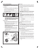
PROGRAMMING REFERENCE PROGRAMMING CONTROL USAGE KEYSTROKES ENTER PROGRAMMING . . . . . . . . . . . . . . . . . . . . . . . . . . . . . . . . . . . . .###MASTER CODE# ESCAPE/CANCEL . . . . . . . . . . . . . . . . . . . . . . . . . . . . . . . . . . . . . . . . . . . . . . . . . . . . . . . . . . . * EXIT PROGRAMMING. . . . . . . . . . . . . . . . . . . . . . . . . . . . . . . . . . . . . . . . . . . . . . . . . . . . . . 99# PROGRAM POSITION NUMBERS (PPN) ENTRY CODE LENGTH . . . . . . . . . . . . . . . . . .
BASIC SYSTEM PROGRAMMING ENTRY CODE PROGRAMMING Entering Programming Mode Setting the Entry Code Length The 6-digit Master Programming Code (default = 123456) is used to enter Programming Mode from a local or remote telephone or the keypad. Master Code Press: Master Code = the current 6-digit Master Programming Code Exiting Programming Mode Press: ✦ NOTE: The RE-1 will automatically exit Programming Mode after five minutes of programming inactivity.
TRANSMITTER PROGRAMMING TELEPHONE PROGRAMMING Adding Transmitters Maximum Number of Visitor Rings Up to 24 groups of transmitters can be assigned common access privileges sharing the same one or two time zones. Up to 100 transmitters total in all groups combined can be used in each RE-1 system.
Call Forwarding Feature Default: OFF The call forwarding feature will allow a visitor to contact the resident at the programmed telephone number instead of through the local telephone line. The feature can be set to be active during a selected Time Zone or at all times. The telephone number programmed can contain an extension number and an optional time delay before dialing the extension.
Relay #2 Alternate Options Default: Access Relay Relay #2 can be used for functions other than triggering a gate operator or door strike. Relay #2 can be programmed to shunt alarm contacts during Relay #1 activation or perform up to five Alarm Functions. Two PPN numbers are used to program the Relay #2 options.
Keypad Beeps On/Off Default: On The default setting causes the main keypad to beep when each key is pressed. The beeps can be disabled. Keypad Beeps Press: Keypad Beeps: 0 = Beeps OFF 1 = Beeps ON Relay #1 Tone On/Off Default: Off The default setting does not cause the annunciator to sound when Relay #1 is activated. The Relay #1 activation tone can be enabled.
Residence Telephone Commands RE-1 OPERATION Requesting Access with an Entry Code • Visitors have up to 40 seconds to key in their entry code. • Up to eight seconds are allowed between each keystroke. • The system can be controlled by the resident without a call from a visitor by using any telephone connected to the local line. • To activate and latch Relay #1 press • All digits of the entry code must be entered. Example: If the code is 0042, the user must enter “0 0 4 2”.
RESIDENT PROGRAMMING QUICK REFERENCE Some of the programming PPN’s may be commonly used by the resident. Following are quick references to the keystrokes required. Maximum Number of Visitor Rings Press: Rings Rings = 1-15 Rings maximum ✦ NOTE: The “###” is the default command prefix. The following example assumes that the default has not been changed.
TROUBLESHOOTING SPECIFICATIONS MECHANICAL Case dimensions: ELECTRICAL Voltage: Current: Backup Battery: Backup Battery Current: System will not go into programming mode 6.45” W x 10.81” H x 3.74” D 1. Wrong master code entered.
PROGRAMMING WORKSHEET TIME ZONES ACTIVE DAYS TIME ZONE SUN MON TUE WED THU START TIME FRI SAT HOLIDAYS HOUR END TIME MINUTE AM/PM HOUR MINUTE AM/PM 1 2 3 4 5 6 7 HOLIDAYS HOLIDAY NAME SYSTEM PROGRAMMING MONTH DAY FEATURE ENTRY CODE LENGTH 1 2 3 4 5 6 7 8 9 10 10 MASTER CODE CALL FORWARDING NUMBER ALTERNATE TELEPHONE NUMBER 1 ALTERNATE TELEPHONE NUMBER 2 ALTERNATE TELEPHONE NUMBER 3 28 PPN DEFAULT 1 4 TX LEFT BUTTON 8 RELAY #1 TX RIGHT BUTTON 8 RELAY #2 TX TOP BUTTON 8
ENTRY CODE RELAY # TIME ZONE ENTRY CODE RELAY # TIME ZONE TRANSMITTER USER __ 1 __ 2 FACILITY CODE ID CODE 1ST TIME ZONE 2ND TIME ZONE TX GROUP __ 1 __ 2 __ 1 __ 2 __ 1 __ 2 __ 1 __ 2 __ 1 __ 2 __ 1 __ 2 __ 1 __ 2 __ 1 __ 2 __ 1 __ 2 __ 1 __ 2 __ 1 __ 2 __ 1 __ 2 __ 1 __ 2 __ 1 __ 2 __ 1 __ 2 __ 1 __ 2 __ 1 __ 2 __ 1 __ 2 __ 1 __ 2 __ 1 __ 2 __ 1 __ 2 __ 1 __ 2 __ 1 __ 2 __ 1 __ 2 __ 1 __ 2 __ 1 __ 2 __ 1 __ 2 __ 1 __ 2 __ 1 __ 2 __ 1 __ 2 __ 1 __ 2 __ 1 __ 2 __ 1 _
LINEAR LIMITED WARRANTY This Linear product is warranted against defects in material and workmanship for twenty-four (24) months. The Warranty Expiration Date is labeled on the product. This warranty extends only to wholesale customers who buy direct from Linear or through Linear’s normal distribution channels. Linear does not warrant this product to consumers. Consumers should inquire from their selling dealer as to the nature of the dealer’s warranty, if any.