PRINTER’S INSTRUCTIONS: INSTR,RA-2400/DVS-2400,REF GUIDE - LINEAR P/N: 217473 C - INK: BLACK - MATERIAL: 20 LB. MEAD BOND - SIZE: 8.500” X 5.500” - SCALE: 1-1 - FOLDING: ALBUM FOLD - BINDING: SADDLE STITCH RA-2400 REMOTE ACCESS SOFTWARE Reference Manual for Programming the DVS-1200, DVS-2400, DUAL-824 & DVS-2408 Supervised Wireless Security Systems WRITER’S NOTE: This publication could contain technical inaccuracies or typographical errors.
TABLE OF CONTENTS 1. GENERAL INFORMATION . . . . . . . . . . . . . . . . . . . . . . . . . . . . . . . . . . . . . . . . . . . . . . . . . . . . 1 1.1 SOFTWARE DESCRIPTION . . . . . . . . . . . . . . . . . . . . . . . . . . . . . . . . . . . . . . . . . 1 1.2 SYSTEM REQUIREMENTS. . . . . . . . . . . . . . . . . . . . . . . . . . . . . . . . . . . . . . . . . . 2 1.3 PROGRAMMING OUTLINE . . . . . . . . . . . . . . . . . . . . . . . . . . . . . . . . . . . . . . . . . . 3 1.4 PROGRAM INSTALLATION . . . . . .
1.1 SOFTWARE DESCRIPTION What is the RA-2400 Remote Access Software? The RA-2400 Remote Access software is a communications program designed to work with Linear’s DVS Supervised Wireless Security Systems and other Linear products. The software runs on an IBM PC or compatible computer and connects to the console through the standard telephone network, or to the Console directly, with the computer’s modem. This 32-bit software runs under all Windows operating systems.
1.2 SYSTEM REQUIREMENTS Minimum System Requirements: IBM compatible 486 personal computer with 8 Mb RAM Windows 95/98/NT/ME/XP/2000 operating systems VGA monitor Name brand modem that is capable of 300 baud (BELL 103 compatible) Hard disk drive with 10 Mb available space for the software plus 18K available space for each Account Profile file.
1.3 PROGRAMMING OUTLINE Use the following programming outline to guide you through the steps required to set up the RA-2400 software and program a DVS-2400 Console. Many of the programming options available in the RA-2400 program can be left in their default settings, and do not need to be changed for most installations. 1. SETUP RA-2400 SOFTWARE ✦ Install the software on your computer (Section 1.4). ✦ Test your computer’s modem (Section 1.5). ✦ Start the RA-2400 program (Section 2.1).
1.4 PROGRAM INSTALLATION The RA-2400 Remote Access Program software is supplied on a CDROM. The installation program will create a directory on your hard disk drive. Be sure that you have at least 10 megabytes free on the hard disk for the program and any Account Profile files that you create. To Install the Remote Access Program: ✦ The first step is to close all other running programs. ✦ Place the Remote Access CD into your computer CD drive. ✦ The installation process should start automatically.
1.5 TESTING THE MODEM Before you run the Remote Access Program, be sure that the computer is running correctly and that the modem is installed and working properly. To Test the Modem: Windows Control Panel can be used to test the modem and determine what COM port it is connected to. ✦ Press START, SETTINGS, CONTROL PANEL. Double-click on MODEMS. ✦ Verify that a modem is shown in the Modem Properties window. ✦ Click on the DIAGNOSTICS tab. The modem installed with the COM port highlighted should be shown.
2. OVERVIEW 2.1 STARTING THE PROGRAM . . . . . . . . . . . . . . . . . . . . . . . . . 7 2.2 NEW WINDOW . . . . . . . . . . . . . . . . . . . . . . . . . . . . . . . . 7 2.3 MENU BAR . . . . . . . . . . . . . . . . . . . . . . . . . . . . . . . . . . 8 2.4 ACCOUNT PROFILE WINDOW OVERVIEW . . . . . . . . . . . . . . . . . 10 ☞ NOTE: Experienced computer or PC users should find that entering data and navigating around the RA-2400 program dialog boxes is similar to most other Windows programs.
2.1 STARTING THE PROGRAM To Run the Program: ✦ Press START, point to PROGRAMS, RA2400 and click on RA2400. 2.2 NEW WINDOW PURPOSE: To select an Account Profile template for the type of unit being programmed. USER RESPONSE: ✦ Select DVS-2400/2408 (with the correct Console firmware version number). ✦ Press OK. The RA-2400 program window will appear with a starter template called DVS-2400/2408 Vx.x-1 showing in the workspace. This file can be stored later, under any name, using SAVE AS...
2.3 MENU BAR PURPOSE: To provide access to each of the programs sub-menus. The sub-menus that can be accessed from this menu are: File NEW To select an Account Profile template for the type of unit being programmed. OPEN Loads a saved Account Profile into the RA-2400 workspace. Multiple Account Profiles can be open at the same time in the RA-2400 workspace. They can be arranged in the workspace using the Window menu on the menu bar, or by dragging them around manually.
2.3 MENU BAR (CONTINUED) VIEW TOOL BAR When checked, the tool bar is displayed. NOTE: The tool bar can be turned into a re-sizable floating tool bar window by dragging it out of its docked location at the top of the workspace. The tool bar accesses many of the popular menu items. Hover the mouse pointer over the tool bar button to see a description of the button. STATUS BAR When checked, the status bar is displayed at the bottom of the workspace. COMMUNICATIONS SETUP...
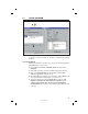
2.4 ACCOUNT PROFILE WINDOW OVERVIEW MENU TREE EDIT AREA PURPOSE: To enter data and make changes to an Account Profile and customize it for a specific installation. MENU TREE Used for selecting the various data entry fields in the Account Profile. Clicking on the plus (+) symbols expands the branches of the menu tree. Clicking on the minus (-) symbols collapses the menu tree branch. Clicking on an item displays the data entry fields in the edit area or other information.
3. COMMUNICATIONS SETUP 3.1 COM PORT . . . . . . . . . . . . . . . . . . . . . . . . . . . . . . . . . . 12 3.2 SPEAKER . . . . . . . . . . . . . . . . . . . . . . . . . . . . . . . . . . . 12 3.3 CONNECTION OPTIONS . . . . . . . . . . . . . . . . . . . . . . . . . . . 13 3.4 MODEM INITIALIZATION STRING . . . . . . . . . . . . . . . . . . . . . .
3.1 COM PORT PURPOSE: To select which communications (COM) port the modem is connected to. USER RESPONSE: ✦ Click on the COM port number (1, 2, 3, or 4) that the modem is connected to. ☞ NOTE: See the TESTING THE MODEM Section (1.5) of this manual for determining the proper COM port number. 3.2 SPEAKER PURPOSE: To set how the modem’s speaker functions before and during communications. USER RESPONSE: ✦ Select OFF to silence the modem’s speaker at all times.
3.3 CONNECTION OPTIONS PURPOSE: To choose how the modem will connect to the DVS-2400 Console. Remote Dialing dials a telephone number with the method chosen (tone or pulse) to connect with the Console over a standard telephone line. Local Cable Connection does not dial a telephone number, but communicates with the Console wired directly to the modem. USER RESPONSE: ✦ Select REMOTE DIALING if the Console is going to be accessed over the telephone line.
3.4 MODEM INITIALIZATION STRING PURPOSE: Used to choose whether the default or a custom initialization “string” is sent to configure the modem (a “string” is a series of characters that are commands for the modem). Modem’s use initialization strings to setup their speed, data type, and other options. The RA-2400 sends the initialization string to the modem before using the modem to connect to the DVS-2400. ☞ NOTE: There are hundreds of models of modems available, each with unique characteristics.
4. CREATING A CUSTOM ACCOUNT PROFILE 4.1 NEW WINDOW . . . . . . . . . . . . . . . . . . . . . . . . . . . . . . . . 16 4.2 CUSTOMER INFORMATION . . . . . . . . . . . . . . . . . . . . . . . . . 17 4.3 CONSOLE ACCESS CODES . . . . . . . . . . . . . . . . . . . . . . . . . 18 4.4 CONSOLE ARM/DISARM. . . . . . . . . . . . . . . . . . . . . . . . . . . 19 4.5 CONSOLE ENTRY/EXIT . . . . . . . . . . . . . . . . . . . . . . . . . . . 20 4.6 CONSOLE ALARMS . . . . . . . . . . . . . . . . . . . . . . . .
4.1 NEW WINDOW PURPOSE: To select an Account Profile template for the type of unit being programmed. USER RESPONSE: NEW ✦ Click on NEW icon on tool bar or select NEW from the FILE menu. ✦ Select DVS-2400/2408 (with the correct Console firmware version number). ✦ Click OK. The new Account Profile will appear as a starter template called DVS-2400/2408 Vx.x-1 (or -2, -3, etc.) in the workspace.
4.2 CUSTOMER INFORMATION PURPOSE: For entering customer information specific to the installation for the Account Profile. USER RESPONSE: CUSTOMER ☞ NOTE: All fields are optional and do not have to be filled in. This information is not sent to the Console. ✦ Enter a CUSTOMER ID for the installation. ✦ Enter the customers name in the NAME field. ✦ Enter the customers address in ADDRESS fields 1, 2, & 3. ✦ Enter the customers telephone number(s) in PHONE fields 1 & 2.
4.3 CONSOLE ACCESS CODES PURPOSE: To install a Master Access Code and up to 5 Restricted Access Codes, a Duress Code, and a Page Alert Code. CODE DEFINITIONS: MASTER ACCESS CODE ✦ Allows arming and disarming the Console. Allows access to all programming options. RESTRICTED ACCESS CODE ✦ Allows arming and disarming the Console. Allows entering and editing Restricted Access Codes.
4.4 CONSOLE ARM/DISARM PURPOSE: To select which modes any remote arm/disarm transmitters will switch to. Also for selection of five arm/disarm options. USER RESPONSE: ARM/DISARM ✦ TOGGLE-ARM TO: Select either HOME or AWAY to choose the mode that any remote arm/disarm transmitters will arm the Console to. ✦ TOGGLE-DISARM TO: Select either OFF or CHIME to choose the mode that any remote arm/disarm transmitters will disarm the Console to.
4.5 CONSOLE ENTRY/EXIT PURPOSE: To select delay times and other options for the Console’s exit and entry delays. USER RESPONSE: ENTRY/EXIT ✦ ENTRY DELAY: To change the entry delay, enter a delay time from 20 to 255 seconds. ✦ EXIT DELAY: To change the exit delay, enter a delay time from 20 to 255 seconds. ✦ BEEP DURING ENTRY DELAY: With this box checked, beeps will sound during the entry delay. Un-check this box to silence the beeps during the entry delay.
4.6 CONSOLE ALARMS PURPOSE: For setting the way the burglary, emergency and fire sirens work. Also sets the options for the home-automation output during and after alarms. USER RESPONSE: ALARMS ✦ BURGLARY ALARM: Select SILENT to disable the burglary siren or select SIREN FOR SET TIME for a timed siren after activation. With timed siren selected, enter the length of time (from 1 to 30 minutes) for the burglary siren to run.
4.7 CONSOLE HOME-AUTOMATION OUTPUT PURPOSE: For setting the way the home-automation output functions. USER RESPONSE: HOME AUTOMATION-OUTPUT ✦ WHEN TRIGGERED: Select TOGGLES to cause the home-automation output to switch between on & off with each activation. Select ACTIVE FOR SET DURATION for a timed home-automation output and enter the length of time 1-2500 (in seconds) for the output to activate. ✦ WHEN ACTIVE: Select OPEN to have the home-automation minus terminal float when the output is active.
4.8 CONSOLE AUDIO PURPOSE: To select how the Voice Board operates. NOTE: The Model VB-2 (for 2-way audio) or VB-3 Voice Board must be installed to use these options. Selects the audio mode for monitoring with the Console’s microphone and communicating through the Console’s speaker to the subscriber. Controls the human voice prompts from the Voice Board.
4.9 SENSORS PURPOSE: To display and edit sensors installed in the Console’s memory. Up to 24 sensors may be installed, each with its own type, restore and supervision options. The status of the sensor selected is also displayed. ☞ NOTE: To display and edit sensors installed in the Console, the sensor data must first be received from the Console (see Section 5.5). USER RESPONSE: SENSOR TYPE ✦ Click on the sensor in the menu tree to view it. ✦ View or edit the SENSOR TYPE.
4.9 SENSORS (CONTINUED) PERIMETER: Sensor will instantly trigger the burglary siren and report the burglary code to the Central Station in Home or Away Mode. Sensor will sound chime in Chime Mode. ENTRY/EXIT: Sensor uses the exit/entry delay and can trigger the burglary siren and report the burglary code to the Central Station in Home or Away mode. Sensor will sound chime in Chime Mode. INTERIOR: Sensor is only active in the Away Mode.
4.10 COMMUNICATOR MAIN PURPOSE: For configuring the Console’s communicator format, dialing method, remote access password, dialing delay, and auto answer options. USER RESPONSE: COMMUNICATOR MAIN ✦ Check the ON box to enable the communicator in the Console. ☞ NOTE: You may want to turn the communicator off while testing the system to prevent the Console from trying to dial out when it is not connected to a telephone line.
4.11 COMMUNICATOR ROUTING AND NUMBERS PURPOSE: For configuring the Console’s communicator account number, trouble report routing, and telephone numbers. USER RESPONSE: ACCOUNT NUMBERS ✦ Enter a four digit account number for the communicator format used. TROUBLE REPORT ROUTING ✦ Select TROUBLE REPORTS TO PRIMARY AND SECONDARY to have trouble reports routed to the primary number for five attempts, then to the secondary number for five attempts before re-trying.
4.12 COMMUNICATOR ENABLED REPORTS PURPOSE: For configuring the Console condition reporting options. USER RESPONSE: ENABLED REPORTS ✦ FORCE-ARM: Check this box to cause the communicator to report arming of the Console to Away Mode with an open and bypassed sensor. ✦ CONSOLE TROUBLE: Check this box to report low Console backup battery and Console backup battery restoral (charged after being low) conditions.
4.13 COMMUNICATOR 4 BY 2 FORMAT ☞ NOTE: Section 4.13 pertains to the 4 by 2 communicator format only. PURPOSE: For configuring how the 4 by 2 format will report to the Central Station. General reporting or Point-to-Point reporting methods are available for the 4 by 2 format. GENERAL REPORTING: General reporting can send five report codes for sensors: FIRE, EMERGENCY, POLICE, BURGLARY and TROUBLE. General reporting does not indicate which sensor caused the report.
4.13.1 4 BY 2 POINT-TO-POINT ALARM CODES PURPOSE: To view and edit the 24 sensor/zone alarm report codes. ☞ NOTE: 4 by 2 Point-to-Point Reporting must be selected (see Section 4.13) for these codes to report. USER RESPONSE: ZONE CODES ✦ Enter a new two-digit alarm code for any sensor/zone that needs to be changed. ☞ NOTE: Entering a “0” for an alarm code will prevent that zone from reporting.
4.13.2 4 BY 2 POINT-TO-POINT TROUBLE CODES PURPOSE: To view and edit the 24 sensor/zone trouble report codes. ☞ NOTE: 4 by 2 Point-to-Point Reporting must be selected (see Section 4.13) for these codes to report. USER RESPONSE: ZONE CODES ✦ Enter a new two-digit trouble code for any sensor/zone that needs to be changed. ☞ NOTE: Entering a “0” for a trouble code will prevent that zone from reporting.
4.13.3 4 BY 2 POINT-TO-POINT ARMING (CLOSING) CODES PURPOSE: To view and edit the force arming report code. This report is sent when force arm is enabled (Section 4.12) and the system is armed with any open sensors that have been bypassed. ☞ NOTE: With either reporting method, the force arming code is the same. USER RESPONSE: ACCESS CODES (CLOSE) ✦ FORCE-ARM: Enter a new two-digit force arming code if it needs to be changed. ☞ NOTE: Entering a “0” for a force arming code will prevent it from reporting.
4.13.4 4 BY 2 POINT-TO-POINT DISARMING (OPENING) CODES PURPOSE: To view and edit the duress report code. This report is sent when the system is armed or disarmed using the duress access code. ☞ NOTE: With either reporting method, the duress code is the same. USER RESPONSE: ACCESS CODES (OPEN) ✦ DURESS: Enter a new two-digit duress code if it needs to be changed. ☞ NOTE: Entering a “0” for a duress code will prevent it from reporting.
4.13.5 4 BY 2 CONSOLE ALARM CODES PURPOSE: To view and edit the five Console report codes. These codes are sent for Console events such as the Console emergency button, fire button, Console low battery and battery restore. The cancel report occurs when the Console is disarmed during an alarm. ☞ NOTE: These report codes are sent for both 4 by 2 General and 4 by 2 Point-to-Point Reporting. USER RESPONSE: CONSOLE ALARM CODES ✦ Enter a new two-digit report code for any Console event that needs to be changed.
4.13.6 4 BY 2 GENERAL ALARM CODES PURPOSE: To view and edit the four general alarm codes and the general trouble code. ☞ NOTE: 4 by 2 General Reporting must be selected (see Section 4.13) for these codes to report. USER RESPONSE: 4 BY 2 GENERAL ALARM CODES ✦ Enter a new one or two-digit report code for any general alarm code that needs to be changed. ☞ NOTE: Entering a “0” for an alarm code will prevent that event from reporting.
4.14 ADEMCO CONTACT-ID REPORT CODES The Ademco Contact-ID reporting codes are pre-defined and cannot be changed. These reporting codes are provided as reference. The Ademco Contact-ID extended report codes indicate the sensor number that triggered the event. Console events report with a “000” extended code. ☞ NOTE: Ademco Contact-ID Reporting must be selected for these codes to report (see Section 4.10).
5. SENDING AND RECEIVING CONSOLE DATA 5.1 ACCESSING THE SEND/RECEIVE WINDOW . . . . . . . . . . . . . . . . 38 5.2 CHOOSING AN ACCOUNT PROFILE . . . . . . . . . . . . . . . . . . . . 39 5.3 CONNECTING TO A CONSOLE . . . . . . . . . . . . . . . . . . . . . . . 40 5.4 SENDING DATA . . . . . . . . . . . . . . . . . . . . . . . . . . . . . . . . 42 5.5 RECEIVING DATA. . . . . . . . . . . . . . . . . . . . . . . . . . . . . . . 43 5.6 CHANGING THE CONSOLE’S MODE . . . . . . . . . . . . . . . . . . .
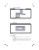
5.1 ACCESSING THE SEND/RECEIVE WINDOW OPEN A SAVED OR NEW ACCOUNT PROFILE CLICK THE SEND/RECEIVE BUTTON PURPOSE: For entering data required to connect to a DVS-2400 Console and to control the connection. Monitors the status of the communication between the RA-2400 and the DVS-2400. USER RESPONSE: ✦ An Account Profile file must be open before the Send/Receive window can be accessed. Use the OPEN... or NEW command in the FILE menu or on the tool bar to load an Account Profile into the workspace.
5.2 CHOOSING AN ACCOUNT PROFILE CHOOSE ACCOUNT PROFILE PURPOSE: For selecting which Account Profile open in the workspace will be used when connecting to a Console. The Account Profile selected automatically fills in the Console’s Phone Number and Password Fields using information already entered in the profile (see Section 2.4). USER RESPONSE: CHOOSE AN ACCOUNT ✦ Click on the desired Account Profile in the Choose an Account box for the Console that is going to be programmed.
5.3 CONNECTING TO A CONSOLE PURPOSE: Causes the RA-2400 to connect to the DVS-2400 Console. The RA-2400 will try to connect to the Console either locally or remotely, depending on the Communications Setup (see Section 3.3). ☞ NOTE: The Communications Setup can be reviewed by pressing the COMM SETUP... button in the Send/Receive window. USER RESPONSE: ☞ NOTE: Before connecting to a Console, it is recommended that all of the sensors used in the system be entered into the Console’s memory.
5.3 CONNECTING TO A CONSOLE (CONTINUED) CONNECTING LOCALLY ✦ Verify that the modem’s LINE jack is connected to the Console’s T&R Terminals with a cable. ✦ Verify that the Console is in Test Mode. ✦ Click the CONNECT button. The Communication Status area will show the progress of the connection. WAIT UNTIL THE TIMEOUT TIMER BEGINS TO COUNT DOWN BEFORE PROCEEDING. ✦ As the timeout timer counts down, PRESS THE EMERGENCY BUTTON ON THE CONSOLE.
5.4 SENDING DATA SEND BUTTON PURPOSE: For transferring data from an Account Profile to a DVS-2400 Console. ☞ CAUTION: Receiving the data from the Console will overwrite the data in the Account Profile. If you have made changes to the Account Profile, save the profile, then send the profile to the Console before receiving the data into the profile. This leaves previously learned sensor information unchanged. If this is a new Account Profile, its OK to receive the Console data into the new profile.
5.5 RECEIVING DATA RECEIVE BUTTON PURPOSE: For transferring data from a DVS-2400 Console to an Account Profile. ☞ CAUTION: Receiving the data from the Console will overwrite the data in the Account Profile. USER RESPONSE: RECEIVING ✦ Click the RECEIVE DATA FROM CONSOLE button. The Communications Status area will indicate the progress and show if the data was received from the Console successfully.
5.6 CHANGING THE CONSOLE’S MODE MODE SELECTION BUTTONS PURPOSE: To remotely view and change the operating mode of the Console. USER RESPONSE: ARMING MODE ✦ View the current operating mode of the Console in the ARMING MODE display area. ✦ To change the current operating mode of the Console, select the desired mode button (OFF, CHIME, HOME, or AWAY) in the ARMING MODE display area. ☞ NOTE: Test Mode and Learn Mode can only be selected directly from the Console’s keypad.
5.7 DISCONNECTING FROM THE CONSOLE DISCONNECT BUTTON PURPOSE: To end the programming session and disconnect the modem from the Console. USER RESPONSE: DISCONNECTING ✦ When finished communicating with the Console, click on the DISCONNECT button. The Communications Status area will show Not Connected when the Console has been disconnected.
5.8 CLOSING RA-2400 EXIT COMMAND PURPOSE: To save the active Account Profile(s) and quit the RA-2400 program. USER RESPONSE: ✦ From the FILE menu, choose EXIT. ✦ To save while exiting, in the SAVE CHANGES? window click YES. If the active Account Profile is the default template, select a location and new name for the file and click SAVE. If the active Account Profile already has a custom file name, it will be saved with the same name.