Black 0001 SECURITY SUPERVISED WIRELESS SECURITY CONSOLE Installation & Programming Instructions (760) 438-7000 • FAX (760) 438-7043 www.linearcorp.
Black INTRODUCTION CONGRATULATIONS for selecting Linear’s DVS-2400 Security System. The DVS-2400 Console incorporates many advanced and sophisticated features. The system can be expanded and customized to fit the installation’s specific needs. The DVS-2400 Console and its accessories are designed and manufactured by the oldest wireless security company in North America. You can look ahead to many years of reliable service with this Console and its accessories.
Black 0003 TABLE OF CONTENTS 1. THE DVS-2400 SECURITY SYSTEM . . . . . CONSOLE . . . . . . . . . . . . . . . . . . DOOR/WINDOW SENSORS . . . . . . . . WIRELESS KEYPAD . . . . . . . . . . . . SMOKE DETECTORS . . . . . . . . . . . . REMOTE CONTROLS . . . . . . . . . . . . PANIC BUTTONS . . . . . . . . . . . . . . BILL TRAP . . . . . . . . . . . . . . . . . . PASSIVE INFRARED MOTION DETECTOR GLASS BREAK DETECTOR . . . . . . . . . . . . . . . . . . . . . . . . . . . . . . . . . . . . . . . . . . . . . . .
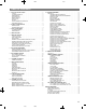
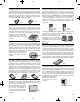
Black 0004 1. THE DVS-2400 SECURITY SYSTEM DXT-41 & DXT-42 REMOTES DXT-21 & DXT-23 REMOTES DXS-21 & DXS-23 REMOTES DVS-2400 CONSOLE DXS-32 DOOR/WINDOW SENSOR DXS-10 WIRELESS KEYPAD DXS-31 DOOR/WINDOW SENSOR DXS-62 & DXS-63 REMOTES DXS-81 BILL TRAP DXS-54 PIR CONSOLE The DVS-2400 Console is the heart of the system. It monitors all of the system’s wireless sensors and controls the alarm sirens.
Black 0005 DOOR/WINDOW SENSORS The DXS-31 & DXS-32 sensors monitor doors and windows. They send radio signals to the Console. One type of signal is sent when the door or window is opened, and a different type of signal is sent when the door or window is closed. If the Console is armed, a sensor can trigger the Console’s burglary siren when its door or window is opened. Both sensors are supervised, and send hourly status reports and monitor battery condition.
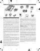
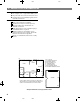
Black 0006 2. SECURITY SYSTEM FLOOR PLAN EXAMPLE SYSTEM ◆ The example shows a typical DVS-2400 system. ◆ Any or all of the accessories shown can be used. ◆ A total of 24 sensors (including keypads) can be used with each Console. DESIGN THE INSTALLATION Create a floor plan of the installation. Consider the security needs of the premises. Determine which doors and windows are vulnerable to intrusion. Figure which interior areas an intruder might go to if unlawful entrance is gained.
Black 0007 3. TYPICAL SYSTEM SENSORS DOOR/WINDOW SENSOR ◆ Sensor mounts on door or window with adjacent magnet. ◆ Opening door or window moves magnet away, triggering sensor. ◆ Internal lithium batteries are monitored by the Console. ◆ Sends hourly status reports to the Console. ◆ Up to 3 years battery life (depends on frequency of activation). WIRELESS KEYPAD ◆ For controlling the system without having to go to the Console. ◆ Emergency and fire alarm can be triggered from wireless keypad at any time.
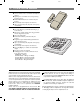
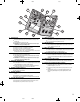
Black 0008 4. CONSOLE FEATURES 3 MODE INDICATORS ★ Specific indicator will light showing the mode the Console is in. ★ HOME indicator will blink during secure exit and home instant modes. ★ AWAY indicator will blink during the exit delay in the Away Mode. 4 CONSOLE STATUS INDICATORS ★ Show the current status of the Console. 5 4 3 POWER LIGHT ★ Glows when AC power is on. ★ Dims when AC power is off and backup battery is installed. ★ Blinks when the backup battery is low, recharging or missing.
Black 13 0009 14 15 16 12 11 10 17 22 18 21 19 20 10 11 12 13 AUXILIARY FUSE ★ Type 2AG, 1-amp fuse. ★ Protects the external relay output when used with wet contacts (12 VDC switched out). ★ Fuse will blow when load exceeds 1 amp. ✍ WARNING: For continued protection against the risk of fire, replace only with the same type and rating of fuse. MAIN TERMINAL BLOCK ★ Terminals for connection to the plug-in AC transformer. ★ Terminals for connection to an external speaker.
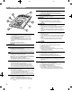
Black 0010 5. CONSOLE INSTALLATION CONSOLE LOCATION ✍ NOTE: Sensor signals must be able to reach the Console. ✔ Try to centrally locate the Console. ✔ Keep Console away from large metal appliances. ✔ Maximum recommended sensor range is 400 feet (system tested at 1000 feet). USE A PAPER CLIP TO REMOVE THE CLEAR DISPLAY WINDOW ✍ NOTE: If you don’t use the Wireless Keypad, the Console should be easily accessible to the usual entrance.
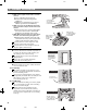
Black EXTERNAL CONSOLE SPEAKER CONNECTION (OPTIONAL) ◆ An external console speaker sounds system tones and alerts occupants with a loud siren during alarm. ◆ With the VB-2 module installed, the Central Station can talk to the occupants through the external console speaker. ◆ Use an 8-ohm, 10 watt minimum rated speaker. Do not use a horn/siren with a built-in siren driver. ◆ Up to two 8-ohm speakers can be used with each Console. ◆ Up to 150 feet of 22 AWG wire can be used with each speaker.
Black TELEPHONE TERMINAL LINEAR SECURITY CONSOLE MODEL DVS-2400 BLOCK TELEPHONE TERMINAL BLOCK SEIZED RING SEIZED TIP TIP RING TO LOCAL PHONES OPTIONAL VOICE MODULE MODEL: VB-2 OR VB-3 SEIZED SEIZED LINE TIP (T1) RING (R1) TIP (T) TO PHONE LINE R T R1 T1 TELEPHONE LINE CONNECTION (OPTIONAL) ◆ Connect the Console to the telephone line if the system is monitored, requires 2-way audio, or requires telephone remote command.
Black CONSOLE POWER CONNECTION ◆ The Console is powered by a low voltage plug-in transformer. ◆ Use up to 25 feet of 20 AWG or larger two-conductor wire to connect the transformer to the Console. Route the power wires from the plug-in transformer to the Console. Connect the wires to the transformer terminals (do not plug the transformer in until the wiring is complete). Route the power wires through the Console’s wiring access hole.
Black 0014 6. BASIC CONSOLE PROGRAMMING ◆ In a new installation, when power is first applied the Console’s master user code is “1234”. CREATE THE MASTER USER CODE ✍ NOTE: Local programming must be entered on the Console’s keypad, not on a wireless remote keypad. Press [∗] (clears keypad if any other keys have been pressed). Place the Console in Test Mode (enter 1234 and press [TEST]. ❇ A “gong” and four “beeps” will sound. Enter the Setup Mode from Test Mode, enter 1234 then press [TEST] again.
Black 0015 PROGRAMMING DIFFERENT SENSOR TYPES ◆ Follow the instructions on the previous page to select a sensor number to program the sensor into. ✍ NOTE: A sensor can be programmed into more than one location. Be sure to choose an unused sensor number. If a sensor gets entered into more than one location, delete the duplicates using the remove sensor function. To add DXS-10 wireless keypads, press and hold the keypad’s [∗] key until programmed into the Console.
Black 0016 7. BASIC SENSOR INSTALLATION ◆ Each accessory sensor is packaged with its own set of installation instructions specific to the model of sensor. ◆ Refer to the sensor’s instructions for details on installing, operating, and testing of the sensor. ◆ Following are basic instructions for installing two popular DVS-2400 accessories: The Model DXS-10 Wireless Remote Keypad and the Models DXS-31 & DXS-32 Door/Window Transmitters.
Black DXS-31 & DXS-32 DOOR/WINDOW SENSORS ◆ The DXS-31 and DXS-32 sensors can be used to monitor doors, windows, cabinets, crawl space doors, gates, freezer doors, and many other moving objects that could be used for intrusion or need to be monitored. ◆ A built-in magnetic switch triggers the sensor when its magnet (mounted on the moving part or the door or window) moves away from the sensor. ◆ External normally closed switches (DXS-31 only) can be wired to the sensor for remote triggering.
Black 0018 8. CUSTOMIZING THE CONSOLE ◆ The Console can be customized for the specific installation. ◆ A label sheet with sensor location names is provided with the Console. ◆ Labeling the sensors allows quick and easy identification of where any alarms have occurred, where a sensor with a low battery is, where a sensor with radio trouble is, etc. LABELING THE SENSORS Use a paper clip to remove the clear display window. Bend down the tabs on the sensor number card and fit it onto the Console.
Black 0019 9. CONSOLE OPERATING MODES OFF MODE ◆ Use this mode to disarm the burglary portion of the system. ◆ Switching to Off Mode stops any alarms in progress. ◆ The 24-hour functions are still active in Off Mode and can be triggered by pressing the [FIRE] or [EMERGENCY] button. Switch to Off Mode by entering the user code, and pressing [OFF]. ❇ When the system is disarmed to Off Mode, the Console will sound one “Gong”.
Black HOME MODE ◆ Use this mode when sleeping or when anyone is staying inside. ◆ Home Mode causes an instant alarm when any perimeter sensor is triggered. ◆ Home Mode causes a delayed alarm when any exit/entry sensor is triggered (except in Home Instant Mode when they are instant). ◆ Alarm siren stops automatically after five minutes and the system will remain armed. ◆ Home Mode ignores all interior sensors (motion detectors, etc.). Arm to Home Mode by entering a user code, and pressing [HOME].
Black AWAY MODE ◆ Use this mode when no one will be staying home. ◆ Each burglary sensor can trigger the siren once per arming period. ◆ Away Mode causes an instant alarm when any perimeter sensor is triggered. ◆ Away Mode causes a delayed alarm when any exit/entry sensor is triggered. ◆ Away Mode causes an instant alarm when any interior sensors (motion detectors, etc.) are triggered. The interior sensors will be delayed if a perimeter delayed sensor is triggered first.
Black 0022 TEST MODE ◆ Even though this is a self-monitoring supervised system, the National Burglar and Fire Alarm Association recommends that all security systems should be tested manually on a regular basis. ◆ The Console must be in Off Mode before going to Test Mode. Switch the Console into Test Mode by entering a user code and pressing [TEST]. ❇ When the system is switched to the Test Mode, the Console will sound a “Gong” and four “Beeps”.
Black 0023 10. SYSTEM TROUBLE INDICATIONS ◆ The DVS-2400 Console is a self-monitoring supervised wireless system. ◆ If the Console detects a problem with any of the supervised system sensors or backup battery, it will display the appropriate trouble indication and, if monitored, report the trouble to the Central Station through the communicator (depending on communicator programming). CONSOLE LOW BATTERY ◆ The Console constantly charges and monitors the optional backup battery (if installed).
Black 0024 11. CUSTOMIZING THE SYSTEM ◆ Adding additional sensors will increase the protection provided by the system. ◆ All ground-level perimeter openings and accessible upper-story openings need protection. ◆ Motion detectors can protect interior areas and areas where valuables are kept. ADDING SENSORS TO THE SYSTEM Always start with the Console in Test Mode (enter a user code and press [TEST]). Enter the master user code then press the [TEST] button. ❇ A “gong” and five “beeps” will sound.
Black MAKING A SENSOR A 24-HOUR DOOR CHIME ◆ Sensors can be programmed to cause the Console to chime any time they’re activated. ◆ Chime-only sensors will not be able to trigger the alarm in any Console mode. ◆ The sensor must have already been learned by the Console (see “Adding sensors to the System” for details). Start with the Console in Test Mode. Enter the master user code then press the [TEST] button. ❇ A “gong” and five “beeps” will sound.
Black 0026 MAKING A SENSOR PERFORM A DIFFERENT FUNCTION ◆ Sensors can be reprogrammed to perform different sensor functions. ◆ The sensor must have already been learned by the Console (see “Adding Sensors to the System” for details). Start with the Console in Test Mode. Enter the master user code then press the [TEST] button. ❇ A “gong” and five “beeps” will sound. ❇ The sensor status indicators will light for each sensor programmed into the Console.
Black 0027 12. ADVANCED PROGRAMMING ◆ To perform any of the advanced programming steps, the Console must be in the Setup Mode. ◆ Each programming function is performed with similar keystrokes. After the Console is in Setup Mode, enter the programming step number, press the [HOME] key (HOME = program), enter the new value, and press the [AWAY] key (AWAY = store). Follow the figures next to the programming steps.
Black CHANGING A SENSORS SUPERVISION ◆ When a sensor is programmed, the Console sets all stationary sensors as supervised, and all portable sensors as non-supervised. ◆ The Console expects hourly status transmissions from any sensor programmed as supervised. ◆ Any sensor can be programmed as supervised or non-supervised.
Black FIRE SIREN TIME ◆ The factory-set fire siren time is five minutes. ◆ The fire siren time can be adjusted from one to 30 minutes. 0029 3 DEF PROGRAMMING STEP #32 2 ABC HOME PROGRAM TIME IN MINUTES (1-30) AWAY AUTOMATION OUTPUT TIME ◆ The factory setting causes the Automation Output to toggle between on and off with each activation. ◆ The Automation Output can be programmed to turn on, then automatically turn off after one to 2500 seconds (42 minutes).
Black SILENT BURGLARY ALARMS ◆ The factory setting causes audible burglary alarms. ◆ Alternately, the Console can be programmed for silent burglary alarms. 0030 6 MNO PROGRAMMING STEP #63 3 DEF HOME PROGRAM 0 FOR AUDIBLE BURGLAR 1 FOR SILENT BURGLAR AWAY SILENT EMERGENCY ALARMS ◆ The factory setting causes audible emergency alarms. ◆ Alternately, the Console can be programmed for silent emergency alarms.
Black 0031 AUTOMATION OUTPUT MODE DURING ALARM ✍ NOTE: For the Automation Output to activate during an alarm, that function must be enabled with Programming Step 71 or 72. ◆ If the Automation output is programmed to 6 MNO PROGRAMMING STEP #68 8 TUV HOME activate during an alarm, it can be programmed to flash or be steady.
Black AUTOMATION OUTPUT WHILE ARMED ◆ The factory setting causes the Console’s Automation Output to activate when pressing the [(A)] key, or when it’s triggered with a two-button remote control. ◆ In addition, the Console can be programmed to activate the Automation Output when the system is armed. AUTOMATION OUTPUT DURING EXIT/ENTRY DELAYS ◆ The factory setting causes the Console’s Automation Output to activate when pressing the [(A)] key, or when it’s triggered with a two-button remote control.
Black ADDITIONAL USER CODES ◆ The Console can be programmed with five restricted user codes and one page alert user code. ◆ The restricted user codes operate the system as usual, but cannot access Setup Mode. ◆ The restricted user codes can access a special Code Mode that can be used to change or remove any of the five restricted user codes, the page alert user code, or the duress code.
Black 0034 13. COMMUNICATOR PROGRAMMING SETUP MODE ◆ To perform any of the communicator programming steps, the Console must be in the Setup Mode. ◆ Each programming function is performed with similar keystrokes. After the Console is in Setup Mode, enter the programming step number, press the [HOME] key (HOME = program), enter the new value, and press the [AWAY] key (AWAY = store). Follow the figures next to the programming step.
Black 0035 GENERAL COMMUNICATOR OPTIONS COMMUNICATOR ENABLE ◆ The factory setting for the Console disables the communicator. If the system is going to be a non-monitored, local alarm only, leave the communicator disabled. ◆ If the system is going to be monitored by a Central Station, enable the communicator with this programming step. 2-WAY AUDIO ◆ When the Model VB-2 voice module is installed, the communicator can provide 2-way audio capability.
Black CALL LIMITER ◆ The factory setting for the call limiter is OFF. This allows the communicator to report burglary alarms, once for each sensor, as many times as they are triggered. ◆ Optionally, the Console can be programmed to only allow five burglary reports total per arming period.
Black 0037 COMMUNICATOR REPORTING OPTIONS REPORTING FORMAT ◆ The factory setting causes the communicator to report using the 4 by 2 format. This format allows four-digit account numbers from 0000 to 9999 and provides two-digit alarm codes. ◆ Alternately ADEMCO CONTACT ID can be chosen as a reporting format. This format allows 4-digit account numbers from 0000 to 9999 and provides verbose report descriptions with Ademco Contact ID compatible Central Stations.
Black ACCOUNT NUMBER ◆ The communicator’s account number entered must be 4-digits long. ◆ The factory setting for the account number is 0000. ◆ Enter an account number from 0000 to 9999. 0038 8 TUV PROGRAMMING STEP #88 8 TUV HOME 4 DIGIT ACCOUNT NUMBER AWAY PRIMARY TELEPHONE NUMBER ◆ The primary Central Station telephone number can be up to 20-digits long. ◆ Digits 0-9 can be used. ◆ Delays and special characters can be entered in the telephone number (see below).
Black REPORT CONSOLE TROUBLE ◆ The factory setting does not report Console trouble events to the Central Station. ◆ Alternately, the communicator can be programmed to report Console trouble events. These include all conditions that light the Console’s BATTERIES or TROUBLE indicator. It also includes low Console backup battery. 0039 PROGRAMMING STEP #108 PROGRAM 0 FOR NO CONSOLE TROUBLE 1 FOR CONSOLE TROUBLE STORE PROGRAM REPORT FORCE ARMING ◆ The factory setting does not send force arming reports.
Black 0040 COMMUNICATOR REPORTING CODES ◆ The two-digit communicator reporting code for each event has a factory set value. These values may be customized to fit the specific installation and the reporting requirements of the Central Station monitoring the system. ◆ If Point ID reporting is enabled (the factory default setting), each sensor can report a unique alarm and trouble code. ◆ If Point ID is disabled, the “general” reporting codes for each event type will be used.
Black 0041 FORCE ARMING REPORTING CODE ◆ Programming Step #258 ◆ The factory set reporting code for force arming is “65” (Code 574 with Ademco). ◆ Any value from 0-99 can be programmed for this event (0 = no report). 2 ABC 5 JKL 8 PROGRAMMING STEP #258 TUV HOME ✍ NOTE: For force arming reporting, force arming PROGRAM 0 - 99 FOR FORCE ARMING REPORTING CODE reports must be enabled. See Page 37.
Black 0042 4 BY 2 FORMAT POINT ID REPORTING CODES 4 BY 2 FORMAT POINT ID ALARM REPORT CODES ◆ Refer to the 4 by 2 Format Point ID Reporting Code table to view/edit the alarm reporting codes for each of the 24 sensors. The communicator will send these codes if Point ID is enabled and any sensor triggers an alarm. The factory settings are listed, along with a blank area to write in the new installation values.
Black 0043 POINT ID REPORTING CODES PROGRAMMING FUNCTION STEP # 210 211 212 213 214 215 216 217 218 219 220 221 222 223 224 225 226 227 228 229 230 231 232 233 234 235 236 237 238 239 240 241 242 243 244 245 246 247 248 249 250 251 252 253 254 255 256 257 SENSOR 1 ALARM REPORT CODE SENSOR 2 ALARM REPORT CODE SENSOR 3 ALARM REPORT CODE SENSOR 4 ALARM REPORT CODE SENSOR 5 ALARM REPORT CODE SENSOR 6 ALARM REPORT CODE SENSOR 7 ALARM REPORT CODE SENSOR 8 ALARM REPORT CODE SENSOR 9 ALARM REPORT CODE SENSOR 10
Black 0044 IMPORTANT INFORMATION LINEAR LIMITED WARRANTY FCC TELEPHONE RULES AND REGULATIONS This Linear product is warranted against defects in material and workmanship for twelve (12) months. The Warranty Expiration Date is labeled on the product. This warranty extends only to wholesale customers who buy direct from Linear or through Linear’s normal distribution channels. Linear does not warrant this product to consumers.