SWR - SWC - SWD Swing Gate Operator Installation Guide IN T E R T E K CM C US L I ST E D Operator models contained in this manual conform to UL325 standard for use in Class I, II, III, and IV applications USA & Canada (800) 421-1587 & (800) 392-0123 (760) 438-7000 - Toll Free FAX (800) 468-1340 www.linearcorp.
Table of Contents Pre-installation Information . . . . . . . . . . . . . . . . . . . . . . . . . . . . . . . . . .1 Before You Begin... . . . . . . . . . . . . . . . . . . . . . . . . . . . . . . . . . . . . . .1 Always Check the Gate’s Action . . . . . . . . . . . . . . . . . . . . . . . . . . . .1 Gate Operator Classifications . . . . . . . . . . . . . . . . . . . . . . . . . . . . . .1 Approved Obstruction Detection Devices . . . . . . . . . . . . . . . . . . . . .1 Safety Information and Warnings . . .
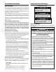
Pre-installation Information Safety Information and Warnings Before You Begin... THE FOLLOWING FORMATS ARE USED FOR SAFETY NOTES IN THESE INSTRUCTIONS. Before unpacking, inspect the carton for exterior damage. If you find damage, advise the delivery carrier of a potential claim. Inspect your package carefully. You can check your accessory box parts with the enclosed packing slip for your convenience. Claims for shortages will be honored for only 30 days from the date of shipment.
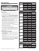
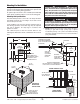
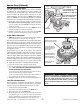
Wiring Specifications Refer to the following steps for details on power and accessory wiring for the operator. VOLTS & HP WARNING 115 VOLTS 1/2-HP ALL AC ELECTRICAL CONNECTIONS TO THE POWER SOURCE AND THE OPERATOR MUST BE MADE BY A LICENSED ELECTRICIAN AND MUST OBSERVE ALL NATIONAL AND LOCAL ELECTRICAL CODES. 230 VOLTS 1/2-HP USE COPPER WIRE ONLY! AC Power Wiring VOLTS & HP 1. Find the listing on this page corresponding to the model, voltage and horsepower rating of your operator. 2.
Mounting Pad Installation WARNING The operator is intended for installation only on gates used for vehicles. Pedestrians must be supplied with a separate access opening. The pedestrian access opening shall be designed to promote pedestrian usage. Locate the gate such that persons will not come into contact with the vehicular gate during the entire path of travel of the vehicular gate. The gate operator mounts bolted to a custom poured concrete mounting pad.
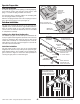
Operator Preparation GEAR REDUCER Vent Plug Installation In order to keep gear oil from spilling out during shipping, gear reducers used in gate operators have either a solid plug, or a sealed vent plug, installed at the factory. REMOVE THE SOLID PLUG WITH AN ALLEN WRENCH For operators with a solid plug, replace the solid plug with the vent plug provided (see Figure 2). With the vent plug installed, remove the vent plug’s breather pin to allow the gear box to vent (see Figure 2).
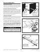
Gate Arm Installation (Cont.) GATES SHOWN OPEN Choosing Good Harmonics Good harmonics are necessary to minimize wear and tear on the operator. The gate will have smoother starts and stops when the arm is installed with good harmonics. Figure 5 shows an example of good and bad arm harmonics. GOOD HARMONICS BAD HARMONICS! Installing the Gate Arm on the Operator The hex cap screws (see Figure 6) in the side of the crank assembly are shipped loose for placement on the operator drive shaft.
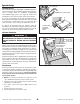
Operator Setup LIFT UP ON TAB Controller Access The Controller in models SWR, SWC and SWD is hinged for access and can be removed without taking off the operator’s cover. It swings down for installation, programming, and troubleshooting access (see Figure 8). Under most circumstances you will not need to remove the Controller. CONTROLLER SWINGS DOWN To access the Controller, lift the metal tab below the AC power switch and swing the Controller down. The Controller is protected by a plastic dust cover.
Operator Setup (Continued) LIMIT SWITCHES (2) Limit Cam Rough Adjustment RIGHT-HAND INSTALLATION TOP CAM - OPEN LIMIT BOTTOM CAM - CLOSE LIMIT The limit cams are not preset at the factory and must be adjusted for each installation. The limit switches are activated by two rotating limit cams attached to the drive shaft (see Figure 10). The Controller is factory set for right hand installations. The top cam is for OPEN and the bottom cam is for CLOSE.
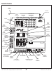
Controller Features WHIP ANTENNA ANTENNA CONNECTOR POWER INDICATORS OPERATION AND PROGRAMMING INDICATORS OPERATION BUTTONS DISPLAY PROGRAMMING BUTTONS SOLAR PANEL TERMINALS INPUT POWER TERMINALS MOTOR BOARD COVER ACCESSORY POWER TERMINALS BATTERY TERMINALS RESET BUTTON TERMINALS PLUG-IN LOOP DETECTOR CONNECTORS PRIMARY/ SECONDARY COMM LINK TERMINALS SINGLE INPUT TERMINALS FIRE DEPT INPUT TERMINALS OPEN INPUT TERMINALS 3-BUTTON STATION TERMINALS SHADOW/RESET OPEN AND CLOSE OBSTRUCTION INPUT TE
Indicator Descriptions INDICATOR DEFINITION OPERATION INDICATION WHEN LIT DURING NORMAL OPERATION PROGRAMMING INDICATION WHEN LIT DURING PROGRAMMING 24 VOLT INPUT POWER LOW VOLTAGE AC POWER IS PRESENT 24 VOLT DC ACCY POWER LOW VOLTAGE DC POWER IS PRESENT OPEN OPEN SIGNAL PRESENT FROM THE INTERNAL RECEIVER OR AN EXTERNAL DEVICE CONNECTED TO THE OPEN INPUT TERMINAL CLOSE CLOSE SIGNAL IS PRESENT FROM A DEVICE CONNECTED TO THE CLOSE INPUT TERMINAL STOP STOP INPUT TERMINAL IS OPEN AND NOT CONNECTED
Terminal Descriptions TERMINAL GROUP AC N AC DC DC + RESET COMMON FUNCTION 24 VOLT INPUT FACTORY CONNECTED TO 24 VAC FROM TRANSFORMER OR 24 VDC FROM CONTINUOUS DUTY DC SUPPLY. ACCESSORY POWER PROVIDES 24 VOLT DC POWER FOR ACCESSORIES. RESET BUTTON FACTORY CONNECTED TO THE CONTROLLER’S RESET BUTTON. COMM LINK FOR 3-WIRE NETWORK CONNECTION TO SECOND OPERATOR IN DUAL GATE INSTALLATIONS. SINGLE BUTTON INPUT CONNECT TO NORMALLY OPEN SWITCH FOR SINGLE BUTTON OPERATION.
Operator Accessory Connections 3-BUTTON STATION TELEPHONE ENTRY PHOTOEYE FOR REVERSE KEYPAD PHOTOEYE FOR CLOSE OBSTRUCTION KEYSWITCH FIRE ACCESS SWITCH SOLENOID LOCK EXTERNAL POWER PHOTOEYE FOR OPEN OBSTRUCTION SINGLE-CHANNEL RADIO RECEIVER MAGLOCK GATE EDGE SENSOR FOR REVERSE TWO-CHANNEL RADIO RECEIVER WARNING STROBE OR AUDIBLE SOUNDER CHANNEL #1 OPEN/CLOSE WIRELESS GATE EDGE SENSOR MGT TRANSMITTER Figure 13.
Basic Controller Programming Programming Overview PROGRAM INDICATOR The Controller can be programmed with various options for the operator. The programming fields are defined as “functions” that have “options”. To make setup easier for the installer, the Controller’s programming is divided into two groups: basic and advanced. The basic programming group contains the functions commonly used in most swing gate installations. The advanced programming group contains functions less commonly used (i.e.
Basic Controller Programming (Cont.) FUNCTION Run Alarm and Pre-start Alarm To detect obstacles or mechanical problems with the gate, the operator monitors its motor current. If the open current load exceeds the programmed maximum load number, the operator will stop, reverse a short distance, then stop again. The Auto Close Timer will be disabled, and another open request will be required to start the operator again.
Advanced Controller Programming FUNCTION Entering Advanced Programming Mode To access and program the Advanced Programming functions, for each programming session, Advanced Programming must be enabled. OPTIONS ADVANCED PROGRAMMING OPTIONS WILL BE DISPLAYED After exiting programming, the Advanced Programming functions will be available on the programming display during the next programming session unless the operator has run 50 or more cycles. After that, Advanced Programming must be enabled again.
Advanced Controller Programming (Cont.) Auxiliary Relay Mode FUNCTION The Auxiliary Relay has normally open and normally closed contacts. The factory setting disables the Auxiliary Relay. The relay can be set for: • Maglock: The relay will energize during any pending or actual gate motion (open only), to deactivate a magnetic or solenoid gate lock. • Ticket Dispenser: The relay will be energized at all times (enabling a ticket dispenser) unless the operator is fully open or in an entrapment condition.
Advanced Controller Programming (Cont.) Soft Start/Stop Duration FUNCTION This function is only used with DC swing gate Model SWD. This function causes the operator to start and stop the DC motor slowly reducing gate wear and tear (at the full open or closed positions only). The factory default sets the Soft Start/Stop Duration to 3 seconds. The Soft Start/Stop Duration can be set from 1 to 10 seconds.
Advanced Controller Programming (Cont.) FUNCTION Radio Enable The Controller contains a built-in MegaCode® radio receiver to allow activation from up to 40 access control transmitters and two Model MGT (gate edge) transmitters. The factory default enables the internal radio receiver. Alternately, the internal receiver can be disabled. OPTIONS INTERNAL RADIO RECEIVER DISABLED "RA" INTERNAL RADIO RECEIVER ENABLED Antenna Installation The Controller is supplied with a local whip antenna installed.
SWR • SWC • SWD SEPARATE PEDESTRIAN GATE REQUIRED 7 FT. MINIMUM DISTANCE AWAY FROM GATE USE RELIEF CUTS AT CORNERS 6 FT. TWIST WIRE FROM END OF LOOPS BACK TO OPERATOR AT LEAST SIX TIMES PER FOOT 2" MAX. Swing Gate Operator Installation Guide - 18 - OPEN GATE PARTIALLY SHOWN 2" MULTIPLE TURNS LOOP SEALANT 3/8" REFER TO LOOP INSTALLATION NOTES FOR DETAILS NOTE: POSITION SHADOW LOOP APPROXIMATELY HALF WAY BETWEEN ENTRY AND EXIT REVERSING LOOPS.
WARNING SWR • SWC • SWD Swing Gate Operator Installation Guide SEPARATE PEDESTRIAN GATE REQUIRED 7FT.
SWR • SWC • SWD Swing Gate Operator Installation Guide - 20 BEAM PATH CARE MUST BE TAKEN TO POSITION PHOTOEYES SO THAT NUISANCE TRIPPING IS MINIMIZED. THIS DRAWING IS INTENDED TO DRAW ATTENTION TO POSSIBLE LOCATIONS FOR THE INSTALLATION OF CONTACT OR NON-CONTACT OBSTRUCTION SENSING DEVICES. OTHER AREAS OF ENTRAPMENT MAY EXIST DEPENDING ON EACH SPECIFIC INSTALLATION.
Dual Gate Installations Two operators can be used in dual gate installations. The operators communicate with each other through the 3-wire COMM LINK terminals. DUAL GATE COMM LINK WIRING OPERATOR #1 SHIELD When one operator activates, the COMM LINK connection signals the other operator to activate. Each operator functions independently, controlling its gate and monitoring its inputs and accessories. A three-wire shielded conductor cable is required to connect two operators together for dual operation.
MGT Obstacle Transmitter Trouble Operation Indications During normal operation, the Controller’s displays will indicate current operating conditions and status. Power-up Display When the Controller powers up, dashes will show on the display for one second, then the firmware version number will be displayed for one second. If any MGT transmitters are used with the operator, their supervision feature will alert the Controller if there is any trouble with the transmitter.
Gate stopping part way open or closed (but no visible obstruction) Troubleshooting Contacting Technical Support For technical questions regarding Linear gate operators, contact the Technical Services Department at: 1-800-421-1587 from 6:30 AM to 4:30 PM Pacific time Operator fails to start A. If the operator has been running a large number of cycles, the motor may have become too hot and tripped its thermal overload breaker.
Model SWR Exploded View 13C 13B 16 13A 2 12 15 13 19 7A 10 14 7B 26 22 11 5 17 18 20 7 3B 23 25 8 3A 9 4 1 3 REF.
Model SWC Exploded View 13C 2 13B 16 13A 15 12 13 14 10 19 26 5 22 11 7 17 18 20 8 3B 1 9 3A 23 25 4 REF.
Model SWD Exploded View 2 28 13C 13B 16 13A 10 13 26 7B 12 15 19 14 22 5 11 7 17 18 20 7A 1 3B 3A 23 9 8 25 4 3 REF.
SWR, SWC, SWD Gate Arm Assembly Exploded View 13 16 17 9 17 8 10 16 17 18 19 16 17 7 17 5 6 4 16 11 13 15 14 16 19 15 2 20 3 1 12 16 19 GATE ARM ASSEMBLY MECHANICAL PARTS LIST REF.
Model SWD Maintenance Battery Maintenance DC Motor Brush Replacement The gel-cell batteries in this operator require no routine maintenance. For assured continued performance, they should be replaced every year. If power is to be removed for one week or more, disconnect the negative wire from the batteries as this will prevent deep discharging. Fully charge before use after storage or upon initial installation. Brushes should be inspected every 100,000 cycles or yearly, whichever comes first.
6-Month Preventative Maintenance Preventative Maintenance WARNING Always disconnect power from operator before servicing. Keep clear of gate during operation. General Linear gate operators are designed for many years of trouble-free operation and, under recommended operating conditions, will require only minimal maintenance. To ensure that a unit is ready for operation at all times, and to preclude serious damage or failure, inspect the unit systematically.
Gate Operator Installation Checklist INSTALLER CUSTOMER ❑ ❑ 1. The gate has been checked to make sure it is level and moves freely in both directions. ❑ ❑ 2. Potential pinch areas have been guarded so as to be inaccessible OR have contact and/or non-contact obstruction sensing devices installed. ❑ ❑ 3. The installer has installed one or more contact or non-contact obstruction sensing devices, in compliance with UL325 requirements for this installation. ❑ ❑ 4.