C6 Z06 Corvette 10 Rib Conversion Kit [LS7 dry sump engine] PN: L220220206 Revision - 0.1 Lingenfelter Performance Engineering 1557 Winchester Road Decatur, IN 46733 (260) 724-2552 (260) 724-0422 fax www.lingenfelter.
Parts List # 1 1 1 1 2 1 1 1 1 1 1 1 1 1 1 • C6 Corvette 10 rib conversion kit, L220220206 8.0” Description Part number 10 rib LS7 OD damper, 8.000” OD at ribs ATI918622 10 rib alternator pulley, underdrive ATI916205 Tensioner pulley, 10 rib, double bearing ATI916186 Power steering pulley and hub assembly, 10 rib ATI916187 10 rib 90 mm smooth idler, double bearing ATI916208 tensioner DAY89418 Corvette 10 rib front tensioner and bracket kit L220010197 M10x1.
Read the entire instruction manual before beginning installation. Some stock parts will be used in reassembly. When referencing the side of the vehicle, the driver side of the vehicle is considered the left side and the passenger side of the vehicle is considered the right side of the vehicle. 1. Open the hood of the vehicle. If you have been driving the vehicle, allow the vehicle to cool down for a few hours before starting this installation. 2.
. Install the LPE supplied 10 rib bracket onto the water pump. Torque the bolts to factory torque specifications. 5. Using a set of calipers, measure the air gap between the head and the bracket. If the space between them is larger than 2.395” then you may need to used the supplied shims to make up the difference. If the gap is smaller than 2.395” you may need to take material off of the spacer. DO NOT TIGHTEN THE BOLT TO MAKE UP FOR THE GAP. 6. Using the supplied M10x1.
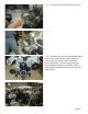
8. You will now need to remove the factory idler pulley and install a ribbed pulley. 9. Using a hammer and a punch, remove the dust cap from the idler. 10. Using an impact gun, remove the idler bolt from the front of the pulley and remove the pulley. The stock pulley and dust shield will not be reused. 11. The original bolt will be re-used. Page 4.
12. Install the supplied 10mm washer onto the tensioner in the position shown. 13. Place the pulley on the tensioner. Apply a small amount of Loctite on the tensioner pulley bolt. 14. Torque the tensioner pulley bolt to 35 lb-ft. 15. Install the two (2) tensioner bolts into the tensioner bracket. Page 5.
16. Torque the two tensioner bolts to 35 lb-ft. 17. 18. Top idler pulley (on front jackshaft bracket) uses M10x1.5x70 stainless socket head cap screw and 0.450” pulley locator behind the 90 mm idler pulley. The lower idler pulley (on the alternator bracket) uses the M10x1.5x60 stainless socket head cap screw and the 0.350” pulley locator. Page 6.
For additional product installation information and technical support, contact LPE or your LPE products distributor. You can also find technical support and usage discussions regarding this product and many other LPE products in our Internet forums: http://www.lingenfelter.com/LPEforumfiles Lingenfelter Performance Engineering 1557 Winchester Road Decatur, IN 46733 (260) 724-2552 (260) 724-0422 fax www.lingenfelter.com FILE NAME Page 7.