Installation Instructions For The Lingenfelter High Flow LS9 Supercharger Front Cover (6.2L LS9 V8 engine) PN: L250110309 Revision - 2.2 Lingenfelter Performance Engineering 1557 Winchester Road Decatur, IN 46733 (260) 724-2552 (260) 724-0422 fax www.lingenfelter.
Parts List LPE LS9 SC cover, PN L250110309 # Part number 1 XX03529-0006 10 47503 1 L960130709 2 SPIR-69427 1 ETN307901 1 82180 1 ETN86063 1 L920030000 1 L450110095 1 L920010000 1 Description LPE LS9 SC front cover assembly Stainless socket head cap screw, M4x0.7x12 Solid SC isolator coupling Supercharger cover alignment dowel pin LS9 pulley cap Permatex Ultra Black Gasket Maker, 3.35 oz.
Lingenfelter High Flow LS9 Supercharger Front Cover, aka “snout”, specifications: • The Lingenfelter front supercharger cover casting was designed to provide a more direct path for the airflow from the throttle body to the supercharger. This provides reduced inlet restriction (reduced pressure drop) resulting in increased boost and reduced supercharger work.
1. Open the hood of the vehicle. If you have been driving the vehicle, allow the vehicle to cool down for a few hours before beginning this work. Some of the pictures in these instructions show the hood removed. This was done to make it easier to take the pictures. Although you can remove the hood in order to provide easier access, it is not required that you do so. 2. Open the rear hatch and open the battery compartment cover.
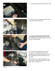
. Remove the plastic loom holder from the factory intake duct but leave the MAF sensor harness loom in the holder. Be careful not to damage the factory plastic fastener. 6. Disconnect the throttle actuator electrical connector from the throttle body. 7. Disconnect the positive crankcase ventilation (PCV) fresh air tube from the passenger side of the air inlet duct. Remove the PCV inlet tube from the air filter bellows by pushing up on the release lever. Next pull the tube free from the air duct barb.
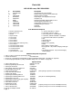
9. Remove the rear hood seal from the cowl. 10. Using a 5/16” nut driver or socket, loosen the clamp on the throttle body 11. Remove the air inlet duct and air filter housing by pulling straight up on the air inlet duct assembly to detach the rubber grommets from the mounting pegs. 12. Remove the supercharger drive belt by using a 1/2” breaker bar to rotate the supercharger belt tensioner and then remove the supercharger belt from the pulleys and tensioner.
13. Disconnect the electrical connector from the supercharger actuator solenoid at the left front of the supercharger. 14. Disconnect the active exhaust vacuum hose that routes from the left side of the engine compartment to the front of the supercharger. 15. Disconnect the brake boost vacuum hose that routes from the left side of the engine compartment to the front of the supercharger. 16. Disconnect the fuel injector and ignition coil harness connector from the driver side of the engine. Page 6.
17. Disconnect the air outlet pressure sensor (boost pressure) harness connector from the sensor on the driver side of the vehicle. 18. Disconnect the PCV fresh air hose line from the left side valve cover (at the rear of the engine). 19. Disconnect the fuel injector and ignition coil harness connector from the passenger side of the engine. 20. Disconnect the supercharger outlet air temperature sensor (IAT2) electrical connector from the sensor on the right side of the intercooler. Page 7.
21. Disconnect the barometric pressure sensor electrical connector on the right side (passenger side) of the intercooler. 22. Disconnect the PCV fresh air hose line from the right valve cover (at the front of the engine). 23. Move the PCV air house assembly out of the way by rotating it up and over. 24. Using a fork type pry tool, carefully pry the wiring harness fastener clip below supercharger boost control solenoid. Page 8.
25. Using a fork type pry tool, carefully pry the wiring harness fastener clip on the front of the driver’s side fuel rail. 26. Using a fork type pry tool, carefully pry the wiring harness fastener clip located on the rear of the driver’s side fuel rail. 27. Using a fork type pry tool, carefully pry the wiring harness fastener clip located on the front of the passenger side fuel rail. 28.
29. Disconnect the ignition coil electrical connectors from the ignition coils on the right side of the engine. 30. Disconnect the ignition coil electrical connectors from the ignition coils on the left side of the engine. 31. Disconnect the purge line from the purge solenoid on the left side of the supercharger front cover. 32. Raise the vehicle with a vehicle hoist or a jack and jackstands.
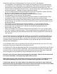
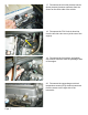
33. Using a 13 mm socket and the 6” extension, remove the sway-bar bushing to cradle bracket bolts (2 per side) and then remove the brackets from both sides. Allow the sway bar to swivel down but do not remove the sway-bar. 34. Using a 21 mm socket, loosen the four engine cradle retaining nuts on both sides. 35. Loosen the engine cradle nuts such that you have roughly a 1 inch (25 mm) gap between the nut and the subframe. You should still have several turns of engagement on the threads on each nut.
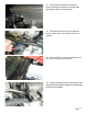
37. Seventeen (17) 10 mm head bolts secure the supercharger cover to the supercharger assembly. 38. Remove the supercharger cover from the engine. 39. With the intercooler fluid lines still connected to the cover, put the cover off to one side of the engine compartment and cover with a plastic bag or rags to prevent dust and debris from getting into the cover. 40. Inspect the supercharger cover seal. Replace if damaged. [GM PART #12613457]. Page 12.
41. Inspect the supercharger insulator seals. Replace if damaged [GM part # 12609472]. 42. Remove the PCV dirty air hose line from the passenger side of the supercharger. 43. Remove gas cap from gas tank. 44. Bleed the fuel system pressure to 0 psi at the service test port on the driver side fuel rail. Page 13.
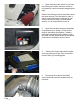
45. On the driver side of the engine, remove the lock and disconnect the fuel feed-to-rail hose from the fuel rail using the J-37088-A fuel line disconnect tool or similar tool (available from LPE, part # MAG69-12-57-001). Use a rag to catch any excess fuel that may spill from the lines. 46. Using a 8 mm socket and extension, remove the supercharger bolts. 47. Ten (10) 8 mm socket head bolts retain the supercharger assembly. 48. With the help of an assistant, remove the supercharger assembly.
49. Cover the inlet area of the supercharger to prevent dirt or debris contamination onto the rotors. 50. Wipe the heads clean of oil using a solvent dampened rag and then vacuum the area of dust and debris. It is very important to maintain a clean work environment. 51. Cover the intake ports on the engine with tape or rags to make sure nothing enters the engine. 52. Inspect the intake manifold gaskets on the supercharger assembly.
53. Using a 10 mm socket, remove the four (4) bolts that secure the throttle body to the supercharger assembly. Remove the throttle body. 54. Disconnect the engine inlet air pressure sensor electrical harness. 55. Using a 10 mm socket, remove the bolt to the inlet air pressure sensor from the supercharger front cover. 56. Using a 10 mm socket, remove the bolt to the purge solenoid from the supercharger front cover. Page 16.
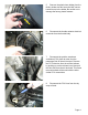
57. Remove all vacuum hoses from the bypass valve actuator and boost control solenoid. Using a 10 mm wrench, remove the two (2) bolts securing the bracket as shown. 58. Carefully remove the throttle body gasket from the front cover assembly. Inspect the gasket. If it is in good condition it will be re-used later on. If it is damaged you will need to obtain a replacement gasket [GM PART #12576549]. 59.
61. Remove the front cover from the supercharger assembly. 62. Remove the spring loaded isolator coupling from the supercharger assembly (or it may be on the front cover assembly). 63. Inspect the cover mounting surface on the supercharger assembly. Clean off any remaining adhesive with a razor blade. If you have powdered rust in the supercharger shaft housing bore, this is from the spring on the isolator contacting the shaft on the front housing and is fairly common. Wipe off the dust. 64.
65. Remove the old dowel sleeves from the front cover/housing. Install the supplied dowel sleeves into the LS9 supercharger housing. Install the sleeves in the bottom left and bottom right hand corner of the supercharger housing. DO NOT install sleeves on the front cover. NOTE: Some early engines may not have dowel sleeves in the cover. Dowel sleeves should be used on these early engines as well. See example image for correct location. 66.
69. Install the throttle body gasket that you removed from the stock front cover onto the new supercharger front cover. If you are using a throttle body larger than 90 mm (stock is 87 mm) and have modified the front cover for the larger throttle body you will not be able to use the factory rubber gasket and you will have to use a paper gasket or liquid gasket material. 70. Install the supercharger pulley onto the hub on the supercharger shaft. 71. Apply a small amount of Loctite Blue to the supplied M4x0.
73. Use the set tool to set the actuator position [tool part # ETN86063]. Place the actuator set tool so that the actuator arm teeth are located in the position shown. Note the bypass set screw position. NOTE: The front cover and bypass actuator are shown off of the vehicle for illustrative purposes only. Bypass set screw 74. Hold the bypass stop plate back so that the bypass valve blade is in the closed position. The stop plate should not be touching the set screw on the bypass actuator.
77. Install the boost control solenoid bracket assembly onto the front cover. Using a 10 mm socket, torque the fastener to 10 Nm (89 lb-in). Replace all vacuum hoses. NOTE: Refer to the diagram on page 35 for the vacuum routing diagram. 78. Install the purge solenoid onto the front cover. Using a 10 mm socket, torque the fastener to 10 Nm (89 lb-in). 79. Install the inlet air pressure sensor onto the front cover. Using a 10 mm socket, torque the fastener to 10 Nm (89 lb-in).
81. If you are using a pulley combination that requires a different idler, replace the factory idler at this time. Follow steps 79 to 81 for installing the new idler. See table 1 on page 37 for information on what size idler is needed for different pulley combinations. 82. The idler to be replaced is the factory 90 mm idler found on the driver side of the vehicle (not the 76 mm idler found near the water pump and tensioner).
85. Make sure the cylinder head and engine area are free of loose debris. Remove the tape from the cylinder head intake ports. NOTE: If you removed the fuel rail and injectors as part of this process, the fuel rail and injectors must be installed prior to the intercooler cover installation. 86. Apply a 5 mm (0.2 inch) band of threadlocker (Loctite Blue, GM PN 12345382 or equivalent) to the threads of the 10 supercharger bolts. Place the ten bolts into the supercharger. 87.
89. Tighten the bolts a first pass in sequence to 5 Nm (44 lb-in). Tighten the bolts a final pass in sequence to 10 Nm (89 lb-in). 90. Remove the tape or other covering material from the supercharger housing. 91. Connect the PCV dirty air hose line to the passenger side of the supercharger front cover. 92. Connect the engine inlet air pressure sensor electrical harness. Page 25.
93. Install insulator seals on the supercharger assembly. 94. If you removed or are replacing the supercharger cover seal, install the supercharger cover seal. 95. Install the seventeen (17) supercharger cover bolts and the supercharger cover. 96. Tighten the bolts a first pass in sequence to 5 Nm (44 lb-in). Tighten the bolts a final pass in sequence to 10 Nm (89 lb-in). Page 26.
97. Reconnect the fuel line and safety clip on the passenger side of the vehicle. 98. Raise the vehicle back up in the air. 99. Using the jack raise the engine back up into position. 100. Using a 21 mm socket, tighten the four engine cradle stud nuts (two on each side) and torque to 110 Nm (81 lb-ft). You can now remove the jack from under the engine. Page 27.
101. Using a 13 mm socket and the 6” extension, install the sway-bar bushing to cradle brackets and bolts on both the left and right side. Torque to 58 Nm (43 lb-ft). 102. Lower the vehicle back down on the ground and re-install gas cap 103. Connect the ignition coil electrical connectors to the ignition coils on both sides (8 coils). 104. Re-install the hood seal on the cowl. Page 28.
105. Connect the PCV fresh air hose assembly to the left and right valve covers and the dry sump tank. 106. Re-attach the three (3) wiring harness fastener clips on the driver side of the vehicle. 107. Re-attach the two (2) wiring harness fastener clips on the passenger side of the vehicle. 108. Connect the IAT2 sensor electrical connector. Page 29.
109. Connect the barometric pressure sensor electrical connector. 110. Connect the boost pressure sensor connector. 111. Connect the fuel injector and ignition coil harness connector on the driver side. 112. Connect the fuel injector and ignition coil harness connector on the passenger side. Page 30.
113. Connect the brake boost vacuum line to the supercharger front cover. 114. Connect the active exhaust vacuum hose to the supercharger front cover. 115. Connect the electrical connector to the supercharger boost control solenoid and connect evap hose to solenoid. 116. Connect the electrical connector to the EVAP purge solenoid. Page 31.
117. Connect the EVAP purge line to the purge solenoid. 118. Install the supercharger drive belt. Depending on your pulley combination this may be the stock belt or a different length belt. See Table 1 on page 35 for recommended belt and idler sizes for the different supercharger pulley and damper diameter combinations. 119. Install the air intake system. NOTE - the LPE LS9 front cover does not work with the stock ZR1 air intake. The LPE ZR1 air intake or a custom fabricated air intake must be used.
121. Connect the mass air flow sensor connector. 122. Re-install the engine sight shield (engine cover) by pushing down on the cover to secure it to the mounting posts. 123. Program the vehicle’s engine control module (ECM) as required for the combination of parts on your vehicle. The different pulley ratio combinations will require different levels of calibration changes but all combinations require some level of calibration changes. 124.
125. DLC port cover kit installation. 126. Install the supplied diagnostic port (DLC port) cover onto the DLC port in the driver foot well. Secure the strap that retains the DLC cover to the vehicle. This cover is meant to notify dealerships and other service facilities that this vehicle has custom programming installed for new supercharger pulley ratio and it should not be programmed with the stock GM calibration files when being serviced. 127.
128. LPE LS9 two piece pulley removal: The Lingenfelter two-piece LS9 pulleys have twelve (12) holes on the face. Ten (10) of the holes are not threaded and these are used to secure the pulley to the hub. The two (2) holes are threaded to accept M4 x 0.7 fasteners. These two holes allow you to use two M4 x 0.7 screws to remove the pulley from the hub. To do so, remove the ten (10) M4x0.7x12 mm fasteners from the pulley and then thread two M4x0.7x14 or longer screws into the two additional holes.
4 7 6 2 NEXT ASSY P 3 USED ON REV. X FINISH O MATERIAL 8 DIMENSIONS ARE IN INCHES TOLERANCES: FRACTIONAL ANGULAR: MACH BEND TWO PLACE DECIMAL 0.005* THREE PLACE DECIMAL 0.001* *UNLESS STATED OTHERWISE SUPERCHARGER PROPRIETARY AND CONFIDENTIAL THE INFORMATION CONTAINED IN THIS DRAWING IS THE SOLE PROPERTY OF LINGENFELTER PERFORMACE ENGINEERING. ANY REPRODUCTION IN PART OR AS A WHOLE WITHOUT THE WRITTEN PERMISSION OF CHECKED DRAWN MFG APPR. ENG APPR. COMMENTS: Q.A.
ADDITIONAL NOTES The 2.38” pulley when combined with our 14% overdrive damper will result in a supercharger speed 23,000 RPM at 6,500 RPM engine speed. Based on LPE testing we do not recommend exceeding 23,000 RPM on the LS9 supercharger. The production GM LS9 fuel injectors and production fuel pump are able to supply the correct amount of fuel for either pulley size so no changes to the injectors or the fuel system are needed if you are only installing the Lingenfelter LS9 cover and supercharger pulley.
Many other items are available from LPE for your ZR1 Corvette including low temperature thermostats, camshafts, ported throttle bodies and much more. Contact LPE, visit our web site, or contact your LPE distributor for information about our other products. For additional product installation information and technical support, contact LPE or your LPE products distributor.