Installation Instructions for 1997-2004 C5 Corvette Mini Tub Kit PN: L350080197 Revision - 1.1 Lingenfelter Performance Engineering 1557 Winchester Road Decatur, IN 46733 (260) 724-2552 (260) 724-0422 fax www.lingenfelter.
Parts List LPE C5 Mini Tub Kit, PN L350080197 # Part number 1 LN-BK14INNER 1 LN-BK15INNER 1 LN-LR WHEELTUB 1 LN-RR WHEELTUB 8 10-24X1/2BSCSSS 8 10-24 NYLOK S/S 4 AV9880 14 AV15373 2 XX09737-0025-A 2 LN-BK17 4 11609489 8 #10 FLAT WASHER 2 AV9880LP 1 AV15414 1 • • • • • • • • • • • • Drill bits 0.140” #28 0.125 1/8” 0.
Read the entire instruction manual before beginning installation. Some stock parts will be used in reassembly. 1. Raise the vehicle with a vehicle hoist or a jack and jackstands. Be careful to follow the GM lifting procedures on the C5 Corvette due to the aerodynamic components being easily damaged and the low ride height of the vehicle. 2. Using a 19 mm socket, remove the rear tires. 3. Remove the carpet and speakers from the rear of the vehicle.
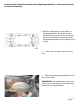
. Locate the two (2) “hat” shaped brackets shown on the left. Draw a line straight back from each bracket so they can later be located in the same front-to-back location. Remove them from both sides of the vehicle. There should be four (4) brackets removed total. 5. Lay out your lines as shown and drill the rivets as shown. 6. Working from the trunk area measure from the vertical wall of the fender-well towards the center of the car, mark at 2 inches and draw a line parallel to the fender-well. 7.
8. The front cut will be against the metal frame, the rear cut should radius in the corner and then go toward the fender-well as shown. NOTE: On hard tops and convertibles the post will need cut as close as possible to the fender-well (this will later be bonded to the new fiberglass tub extension). Coupes will need the speaker box cut free from the fender well, leave as much of the speaker box as possible, the cut should not enter into the round speaker hole. 9.
12. After fitting the fiberglass tub extension to the cuts, trim or sand the post as necessary for good fitment. NOTE: On coupes, the speaker box will need to be trimmed. 13. Trim the tub extension for a good fit. Make sure it does not hang over the storage compartment. Notch out the fiberglass for the raised area in the floor and sand for clearance of the button-head screws. 14.
16. Remove the fiberglass and scuff all mating surfaces with a high grit sandpaper. Apply a sufficient amount of Plexus, Durabond or similar bonding agent to obtain a watertight seal. Install and pop the rivets into place. 17. Using a fiberglass repair kit, re-attach the post on the hardtop or convertible speaker box on the coupe. Silicone the edges to ensure a watertight joint. 18. You will now install the plastic inner fenders on the vehicle. Start by locating the access panel on the inner fender. 19.
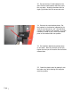
20. Re-use the two (2) hat brackets in the same front-to-back locations but flush out to the new edge. Install the brackets with the eight (8) provided #10-24 screws and nuts. 21. Remove the rear brackets shown. Cut the brackets in the direction indicated by the white line and shorten by 1/4” (this will allow a larger inner fender to be inserted). It is then necessary to weld or pop rivet the shortened piece on the bracket back into position. 22. Re-install the brackets by placing them on the studs.
24. Work the panel into location from front to rear. At the rear, the “U” notch in the panel should snap in location over the body panel joint, start it in low and force it up. 25. Mark the high spots on the panel if the fitment is not good and trim if necessary. Reinstall the panel. 26. While seated and facing the rotor, reach under with your left hand and pull the triangular section of the top center of the panel towards you so it is tight against the returning flange of the body.
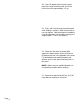
28. Use a 90 degree pick to pull the panel tight to the other mounting hole; this is the hole to the front approximately 11” up. 29. Drill a 1/8” hole through the plastic panel while holding in position, install a screw but do not over tighten. Before permanent installation it will be necessary to trim plastic to accept the supplied black “J” nut in this location. 30.
32. Drill out the hole in the triangular section to 1/4”. 33. Use one of the black screws provided to fasten the small rectangular plate with the “J” nuts to the backside of this hole. 34. Drill 1/8” holes through existing holes in the rectangular plate and through the plastic. Pop rivet into position from the bottom side up. 35. Install the other “J” nut as previously mentioned. Make a reference mark in the top section where the raised area of the panel comes in contact with the body.
36. Measuring from the reference mark that you made on the body, locate and drill the plastic panel so you can use the stock threaded hole. 37. Remove the rear shocks from the vehicle. Pull the dust cover boot off of the shaft of the shock, slide the supplied the round black plastic spacer onto the shaft and re-install the dust cover boot. 38. Install the shocks using the supplied shock brackets. The machined depression on the bracket should face downward. 39.
40. Install the bottom screw first and pull tight as previously explained while a helper tightens the screw. Start all screws but do not tighten them yet. 41. While pushing tight against the frame, drill a 1/8” hole through the top supplied hole into the sheet metal. Install the shortest screw and tighten. WARNING: DO NOT PUSH DRILL BIT THROUGH ANY MORE THAN NECESSARY. FUEL SYSTEM COMPONENTS ARE ON THE OTHER SIDE. 42. Tighten all other screws and install the two bolts into the modified bracket. 43.
44. Remove the matting that rests on the vertical walls of the fender-wells and the excess matting in a 2” strip running the length of the fender-well. 45. Sand the plastic panels that come in contact with the fender-well as necessary, remove the staples and re-install the carpet. There are some sections that you will need to trim in order to fit the new tub kit. NOTE: If your vehicle comes equipped with a storage compartment you will need to trim the carpet as necessary to fit. 46.
For additional product installation information and technical support, contact LPE or your LPE products distributor. You can also find technical support and usage discussions regarding this product and many other LPE products in our Internet forums: http://www.lingenfelter.com/LPEforumfiles Lingenfelter Performance Engineering 1557 Winchester Road Decatur, IN 46733 (260) 724-2552 (260) 724-0422 fax www.lingenfelter.com L350080197 C5 mini tub kit install 1.1.indd Page 14.