Installation Instructions for Lingenfelter RPM-002 Digital RPM Controlled Switch PN: L460040000 1557 Winchester Road Decatur, Indiana 46733 260 724 2552 phone 260 724 8761 fax www.lingenfelter.
# 1 1 2 1 1 • Part number RPM-002 AV16037 L920010000 LED (for shift or indicator light) • Red LED (12 volt, 30 cm wire) • Green LED (12 volt, 30 cm wire) Sealed 40 amp heavy duty relay kit MPH activated switch • • Parts List Description LPE Digital RPM Controlled Switch hook & loop tape self-tapping screw LPE decal instructions Optional Items L450030000 L450040000 L450100000 L460050000 Specifications: · The Lingenfelter Performance Engineering RPM-002 RPM Controlled Switch incorporates a precision
Table A - Wiring (also labeled on module): Wire color White Yellow Label Tach Normally Off Gray Normally On Black Red Ground +12 Vdc Notes This is the RPM input wire. This connects to your RPM signal wire. This is the normally open (off) activation wire. This wire connects to ground when switch is activated. This connects to the ground side of the device you plan to activate. This is the normally closed (on) activation wire. This wire will open the ground path when the switch is activated.
Installation: • • • • • • • • • • • Disconnect the negative battery terminal. Connect black wire of RPM switch to a suitable vehicle ground. Connect the red wire to a switched and fused +12 volt DC source. Connect the white wire to the RPM signal source. This can be the tachometer output lead of the vehicle, the switched side of the ignition coil (negative side) or the 5 volt RPM reference signal.
Most GM V8 electronic fuel injection (EFI) engine applications including L98, LT1 and LT4 engines (connect white Tachometer Input Signal to ECM/PCM TACH output) • 7200 RPM switch point example o Sixteen position Input Signal Pulse Per Revolution switch set to Low Range and 4 pulses per revolution o RPM programming switch for hundreds of RPM (0X00) on position 2 o RPM programming switch for thousands of RPM (X000) on position 7 Most traditional single coil V8 engine applications (connect white Tachome
Window switch mode programming instructions: To Enter/Exit RPM Window Mode: 1 – With power off, set the two switches to 0 and the Input Signal Pulse Per Revolution to Low Range 0.5 pulse per mile (as shown in the image below) Low Range 4 3 2.5 2 1.5 High Range 5 .5 1 1.5 +10,000 Rpm 2 2.5 3 4 1 .
To set a new Low RPM, follow instructions to switch back to Normal mode, and then back to Window Mode and set Low RPM as outlined above. Normal Mode Power Up – The Red LED will come on steady at power up. Normal Mode Error – If the RPM is set for less than 500 the Red LED will blink five times per second until the RPM-002 is powered down and a valid RPM is set. Normal Mode Operation – When in Normal Mode when the set RPM is reached the Outputs will be active.
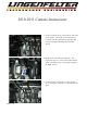
2010-2011 Camaro Instructions 1. Locate coil pack one (1) on the driver side front of the engine. The ECM on 2010 and newer Camaros does not conatin the signal wire that is needed for the LPE RPM-002 activation switch. 2. Remove the coil electrical connector. The purple wire in pin C of this electrical connector is the wire that must be used for input signal to the RPM switch. 3. Connect to this wire using a 2-1 butt connector or equivalent. Make sure to heat shrink the wires.
Table C Table D RPM in thousands (X000) RPM in hundreds (0X00) 0 to 9 equal to 0 to 9000 RPM (in LOW) or 10000 to 19000 (in HIGH) RPM Switch setting LOW mode HIGH mode 0 0 10000 1 1000 11000 2 2000 12000 3 3000 13000 4 4000 14000 5 5000 15000 6 6000 16000 7 7000 17000 8 8000 18000 9 9000 19000 0 to 9 equal to 0 to 900 RPM (in LOW or HIGH) Switch setting RPM 0 1 2 3 4 5 6 7 8 9 0 100 200 300 400 500 600 700 800 900 Table E Pulse/rev 0.5 Low Range RPM mode High range RPM mode 1 1.5 2 2.5 3 4 5 0.