Installation Instructions for 2005-2007 Chevrolet Corvette Lingenfelter High Flow Air Intake System (6.0L LS2 V8 engine) PN: L650070105 1557 Winchester Road Decatur, Indiana 46733 260 724 2552 phone 260 724 8761 fax www.lingenfelter.
# Part number 1 LN4230-AB 1 LN4230-AI 1 L660070105 11 AV17222 2 AV15414 1 TFC30GNB392X2.5 1 LN4230-001 1 53980100 4 53990110 1 539100120 1 93695 K72 1 L670010105 1 1 L920010000 1 • • • • • • • • • Parts List Description LPE C6 Corvette airbox and bracket assembly LPE C6 air-bridge LPE C6 Corvette air intake system air filter push-lock plastic rivet fastener (pin lock style) Christmas tree style plastic fastener 3.9” x 2.5” hose, black 4.
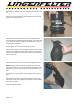
Read the entire instruction manual before beginning installation. Some stock parts will be used in reassembly. • Disconnect battery ground. • Remove gray retaining clip on the bottom side of the MAF sensor, then disconnect MAF sensor connector. • Disconnect breather tube from bellows. • Loosen hose clamp at throttle body, pull bellows from the throttle body. • Work entire assembly free from push pins & remove assembly from car.
The following steps need to be performed from underneath the vehicle: • Remove the three 7 mm screws holding the front fascia inside the radiator opening. • Next, remove the 7 mm screws on either side (one on each side). These are the screws holding the bottom of the bumper cover - see picture. Remove the two plastic push lock plastic fasteners holding the radiator shroud to the bumper beam. Remove the two plastic Christmas tree fasteners from each side of the radiator shroud.
Install top radiator shroud ensuring it engages fan shroud in the center as shown. Tuck water hose back into holders on shroud, secure with four bolts previously removed. The following steps need to be done from underneath the vehicle: • Replace the previously removed four factory Christmas tree fasteners retaining the shroud to the plastic side panels (two per side). • Replace the five 7 mm head screws previously removed.
Install the 3.9” straight hose on the other side of the MAF sensor. Slide a 90-110 mm clamp over the straight hose section and position the clamp as shown. Slide another 90-110 mm clamp over the straight hose section and attach the supplied plastic air-bridge to the other end of the 3.9” hose with the nipple on the hump hose in the 10 o’clock position as shown. Do not tighten the 90-110 mm clamp at this time. Note position of logo on the air-bridge.
Thoroughly clean edge of airbox with supplied alcohol pad. Cut the supplied foam seal to fit airbox as shown in image. Install rubber seal to three edges of airbox as shown. Make sure the foam seal does not interfere with the mounting holes. Slide airbox and filter assembly in place as shown. Place the remaining 90-110 mm clamp on the hump hose and connect the 4.0” hump hose to the throttle body. Push the hose firmly as shown to seat the hump hose onto the throttle body.
Tighten the clamp retaining the air-bridge to the air filter. Note: This clamps best when the hose clamp is positioned as pictured. Tighten clamp on opposite end of air duct. NOTE : PUSH DOWN FIRMLY ON AIR DUCT WHILE TIGHTENING THIS CLAMP. This is necessary to achieve proper alignment. Double check all hose clamps for tightness. Reattach MAF sensor connector and the gray retaining clip. Reconnect the outside air temperature connector and the hood light connector. Reconnect the battery ground cable.