54 Mbps Wireless Access Point Model #: GT701AP Firmware version: 3.0.1.0.
Table of Contents 1 Introduction 3 Package Contents Minimum System Requirements Access Point Features Technical Support 2 Wireless Networking Basics 3 3 4 6 7 Creating a Wireless Network Extending a Wired Network 7 8 3 Installing the Access Point 10 Before Installing Connecting the Access Point Placing or Mounting the Access Point 4 Setting Up the Access Point Making a Connection Accessing & Viewing the Control Panel Basic Settings Security Settings Advanced Settings 10 10 11 12 13 13 15 17 19
2
1 Introduction Thank you for purchasing the Actiontec 54 Mbps Wireless Access Point. We’ve worked hard to make this Access Point the simplest, most convenient way to create a wireless network for your home office or small business. If you want to take your computing to the next level, the Actiontec 54 Mbps Wireless Access Point is one of the keys to your success.
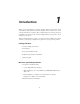
s All computers included on the wireless network must have wireless networking capabilities Access Point Features The Access Point has a series of LEDs on its front panel, and a series of ports on its rear panel. It is recommended that the user become familiar with these features before installing or setting up the Access Point. Front Panel There are three LEDs (light emitting diodes) on the front panel of the Access Point, as shown in the figure, below.
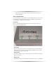
intermittently when there is wireless activity. Rear Panel The Access Point has a Power Connector, A LAN (Ethernet) Port, an Antenna Jack, and a Reset button on its rear panel. LAN Port The Ethernet (LAN) port is used to connect the Access Point to a hub or router with the Gray Crossover Ethernet cable. Power Port The Power Port is used to connect the Access Point’s Power Adapter. Antenna Jack The Antenna Jack connects the Access Point to its antenna.
Technical Support Actiontec Electronics, Inc., prides itself on making durable, high-quality, highperformance products. If you need assistance, the Actiontec Technical Support Department is available to provide professional support 24 hours a day, every day, except major holidays. Actiontec Electronics, Inc. 760 N. Mary Avenue Sunnyvale, CA 94086 Technical Support Phone: 1-888-436-0657 (USA), 0845 65 80411 (UK) Email: http://support.actiontec.com/email_support/support_form.
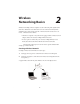
Wireless Networking Basics 2 Wireless networking connects computers to each other using radio signals rather than wires. This allows users the freedom to move around and work anywhere within the range of the wireless network. A wireless network consists of two elements - Clients and Access Points. • A Client is a computer or any other device equipped with a wireless network adapter, such as the Actiontec 54 Mbps Wireless PC Card .
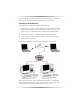
All of the wirelessly networked computers (also known as clients) communicate with each other through the access point, which acts as a wireless hub. Extending a Wired Network To add wireless networking to an established wired network: 1. Connect the access point(s) to the wired network. This is usually done with an Ethernet cable connecting a wired network hub or router to an access point using a “cross-over” style Ethernet cable (included in the Quick Start Kit). 2.
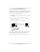
Creating a Wireless Network from a Single Computer It is also possible to connect an access point to a single computer, instead of a network hub. This method can be used to share the computer’s Internet connection among the wireless clients, and is a common way to use a wireless network in the home. To create a wireless network from a single computer: 1. Connect the access point to the computer. Use a standard Ethernet cable (purchased separately). 2.
3 Installing the Access Point Before Installing Before installing the Access Point, be aware that this device can subject the user to electrical shock. Follow the guidelines in this manual and the manuals of any other equipment used during the installation. Failure to do so may result in injury or damage to the equipment. Important: This Access Point is a 2.4 GHz low-power RF device. It is intended for home and office use in all EU member states except France, where restrictive use applies.
2a. If connecting to a Router, hub or switch for wireless network usage or for administration of an access point (using the Web Configuration Utility to change an access point’s settings, for example), plug one end of Gray Crossover Ethernet cable (included in this Quick Start Kit) in the LAN port on the back of the Access Point, and plug the other end into the computer. See figure below. + Note: Do not use the Ethernet cable included with the Access Point Quick Start Kit to connect to a computer.
4 Setting Up the Access Point The 54 Mbps Wireless Access Point is shipped ready for immediate use. Its factory default settings allow the user to access the wireless network after making a few adjustments to the wireless clients to recognize its pre-programmed SSID. You should note however that in its default mode, your Access Point has its security options disabled and is pre-configured to run on channel # 9 of its 11 available channels.
Your connection to the Access Point should be established and you are ready to access to the unit’s control panel. Accessing & Using The Control Panel Making Sure Your Computer Can Talk To The Access Point . The Access Point’s control panel has an internal IP address of 192.168.0.240 which enables any standard web browser to view and adjust its settings. If you are connected to your access point via an Actiontec brand router, it has an address that is within the same subnet address range.
3. The "Welcome" screen appears. From this point, you can configure the Access Point from one of its seven sub-menus Setting the IP Address The IP Address section allows you to setup IP Address, either DHCP or static IP mode. NOTE: Changing these settings is not required in most applications Click on the “IP Address” selection and the “IP Address” page will appear. Actiontec recommends keeping the unit’s default static IP address (192.168.0.
Basic Settings Click on the “Basic Settings” selection and the “Basic Settings” page will appear. This menu allows you to change the Wireless Network Name (ESSID*), from its default value, change the Operating Channel**, and enable one of several available security options***. * ESSID is the network name assigned to the wireless network. The factory default setting is “ACTIONTEC.” The ESSID value can be modified if needed, using any combination of alphanumeric characters (i.e., A-Z, a-z, 0-9).
64-bit WEP uses a key made from of five hexadecimal digit pairs. A hexadecimal digit consists of an alphanumeric character ranging from 0-9 or A-F. An example of a 64-bit WEP key is: 4E-A3-3D-68-72. To create a set of 64bit WEP keys, enter five hexadecimal digit pairs into the desired Key text box (Key 1, Key 2, Key 3, Key 4). 128 bit WEP Key is just like the 64-bit key except that it uses 13 hexadecimal pairs to provide more secure encryption.
The "Both" setting allows stations to use either authentication mode . WEP 802.1x Security The 802.1x protocol is a collection of security features intended primarily for enterprise computing environments. It simplifies management by applying the same authentication protocol for wired and wireless connections. 802.1x offers an effective framework for authenticating user traffic to a protected network, and dynamically varying encryption of keys, and supports multiple authentication methods.
WPA Security The WiFi Protected Access (WPA) protocol is a collection of interoperable security enhancements intended for use in both consumer and enterprise settings. It is a forward-compatible subset of the upcoming 802.11i security standard that greatly improves on the WEP security standard.
and WPA is enabled. If you wish to enable 802.1x, continue to step 4 of this procedure. To Enable WPA with 802.1x: 4. Enter the radio server's IP address in the Server Address box - This address is obtained from the administrator of the radio server. 5. Enter the port number. The normal default value is 1812 unless the network administrator changes it to match a particular radio server’s port setting. In this case, consult your network administrator for the proper setting. 6.
MAC Authentication (Access Control) The “MAC Authentication” screen, gives a user the option of controlling who can talk to the Access Point access based on the user client’s MAC address. This is done using entries on the “Exceptions List” to block or accept a group of potential users. - Enabling the “Deny” mode prevents any client from using the Access Point UNLESS it is on the Exceptions List. - Enabling the “Accept” setting opens up the Access Point to all users EXCEPT those on the exception list.
NOTE: Ensure the MAC Address entered is in the correct format (i.e., six sets of two hexidecimal numbers separated by colons). A properly formatted MAC address would be the following: 00:20:ea:08:00:17 If an incorrectly formatted MAC address is entered, an error message stating that an invalid MAC address has been entered appears. If this occurs, enter a properly formatted MAC address. Information The “Information” screen contains the Access Point’s current configuration information.
2. Be sure to enter password a second time in the Re-enter New Password text box, 3. Click Apply. If you want to disable the password mode after it has been activated, you must select the "Restore Default" button on this page. If you receive the Access Point after it has had a password set but do not know what it is, you can disable the password mode without accessing the control panel by physically resetting the access point.
the 802.11 Wireless networking protocols. Before you do this, you must download the desired upgrade image files from the Actiontec web site (www.actiontec.com) to a selected folder on your computer. The files will be downloaded to you in a self-extracting ZIP format. Before returning to your access point, make sure to "unzip" the files.
Troubleshooting & FAQs 5 This chapter details some potential problems that may occur while using the Access Point, and solutions to overcome them. Also included here are frequently answered questions and their respective answers. Troubleshooting My computer’s THE ACCESS POINT Wizard doesn’t locate the Access Point. There are several possible solutions when this occurs: s Check the Power LED and ensure the Access Point’s power cord is connected correctly.
How fast is the wireless network? The rated speed of the wireless network under optimal conditions is 54Mbps. This speed does vary, depending on distance from the Access Point and the amount of attenuation (physical barriers such as walls, glass, etc.) the wireless signal must go through.. Can I share my Internet connection using the Access Point? Yes, but you need additional equipment.
If I installed several Access Points in different locations in my building, will they be able to talk to each other? Will I be able to stay connected as I moved between them? The Access Point does not communicate with other access points, as it uses a single access point system. If you installed several Access Points and were to move between coverage areas, your wireless device would actually have to reconnect to a separate network.
How do I make a HEX-based WEP key? 64-bit WEP Key - Composed of 10 alphanumeric characters (0-9, a-f) (example: 843c29a562) 128-bit WEP Key - Composed of 26 alphanumeric characters (0-9, a-f) (example: 3c29f2536bef3276d32e364a2c) What is the difference between 40-bit and 64-bit encryption? There really is no difference between the two. They are different terminologies used throughout the industry for the same level of encryption.
Setting Up Static IP A Configuring your Access Point via a direct connection to your computer requires that you set up what’s known as a “static IP address” on your computer’s Ethernet connection. You may also need a static address if you’re “talking” to the Access Point via a switch or router that’s not manufactured by Actiontec. But even if you’re not quite sure what this means, don’t panic - we’ll walk you through step-by-step procedures that will make it relatively painless.
3. Another menu appears. Select Control Panel. 4. When the “Control Panel” window appears, double-click Network.
5. The “Network” window appears. In the "The following network components are installed" list box, locate and double-click TCP/IP. 6. The “TCP/IP Properties” window appears. Select IP Address.
7. In the IP Address tab, activate “Specify an IP Address” by clicking on the circle. When active, a black dot will appear in the circle. If the circle already contains a black dot, leave it alone. 8. Enter the following numbers in the “IP Address” text box: 192.168.0.2 Don't include the periods; they are automatically entered. 9. Enter the following numbers in the “Subnet mask” text box: 255.255.255.0. 10. Click OK. The TCP/IP Properties window disappears. 11. In the Network window, click OK.
Windows Me 1. From the desktop, click on the Start button in the lower left corner. 2. From the menu that appears, select Settings. 3. Another menu appears. Select Control Panel.
4. When the “Control Panel” window appears, double-click Network. 5. The “Network” window appears. In the “The following network components are installed” list box, locate and double-click TCP/IP.
6. The “TCP/IP Properties” window appears. Click IP Address. 7. In the IP Address tab, activate “Specify an IP Address” by clicking on the circle. When active, a black dot will appear in the circle. If the circle already contains a black dot, leave it alone. 8. Enter the following numbers in the “IP Address” text box: 192.168.0.2 Don't include the periods; they are automatically entered. 9. Enter the following numbers in the “Subnet mask” text box: 255.255.255.0 10. Click OK.
Windows 2000 1. From the desktop, click on the Start button in the lower left corner. 2. From the menu that appears, select Settings. 3. Another menu appears. Select Control Panel.
4. When the “Control Panel” window appears, double-click Network and Dialup Connections. 5. In the “Network and Dial-up Connections” window, double-click Local Area Connection. A number may be displayed after the Local Area Connection. If there is more than one Local Area Connection listed, locate the one that corresponds to the network card installed in the computer by finding the name of the network card in the Device Name column.
6. The “Local Area Connection Status” window appears. Select General, then click Properties. 7. The “Local Area Connection Properties” window appears. Click General. 8. In the “Components checked are used by this connection” list box, doubleclick Internet Protocol (TCP/IP).
9. The “Internet Protocol (TCP/IP) Properties” window appears. 10. In the General tab, activate “Use the following IP address” by clicking on the circle. When active, a black dot will appear in the circle. If the circle already contains a black dot, leave it alone. 11. Enter the following numbers in the “IP Address” text box: 192.168.0.2 You don't have to include the periods; they are automatically entered. 12. Enter the following numbers in the “Subnet mask” text box: 255.255.255.0 13. Click OK.
Windows XP 1. From the desktop, click on the Start button in the lower left corner. 2. From the menu that appears, select Connect To. .
3. When the Connect To sub-menu window appears, select the Show All Connections option.
4. The NetworkConnection window appears. Right click on Local Area Connection and select Properties. 5. The Internet Protocol (TCP/IP) Properties window appears.
6. In the General tab, activate “Use the following IP address” by clicking on the circle. When active, a black dot will appear in the circle. If the circle already contains a black dot, leave it alone. 7. Enter the following numbers in the “IP Address” text box: 192.182.0.2 Don't include the periods; they are automatically entered. 8. Enter the following numbers in the “Subnet mask” text box: 255.255.255.0 9. Click OK. The Internet Protocol (TCP/IP) Properties window disappears. 10.
B Specifications Actiontec 54Mbps Wireless Access Point Networking Solution Featuring Scalability and Security Actiontec's 54Mbps Wireless Access Point sets the standard for next-generation high performance, secure, manageable, and reliable wireless local area networks (WLANs). This powerful device provides the ultimate in continuous industry-standard 54 Mbps access to network resources such as, e-mail and the Internet for a wireless workforce. In addition, it is backward compatible to preserve your 802.
neously. Dynamic rate shifting enables the fastest possible connections. Auto Network Connect keeps users connected to the network even while roaming. Usability It is cost effective, simple to install and use. Appropriate for placement above drop-down ceilings and under raised floors. Equipped with convenient Webbased interface. Features · Advanced Security provides advanced 64 bit WEP, 128 bit WEP and 256 bit WEP Security features also support 128 bit encryption WPA 802.
Specifications Interface 10/100 Ethernet LAN Port -RJ45 Power (external adapter supplied) Wireless - IEEE 802.11b Radio output 17.2 dBm - IEEE 802.11g Radio output 11.1 - 16.6 dBm 11 Channels in the U.S.A (13 in Europe) Data Rates 11Mbps IEEE 802.11b 54Mbps IEEE 802.
Features Standard bridging and filtering Infrastructure Mode: BSS (DCF & PCF) Web Server Roaming BPSK, QPSK , 16QAM ,OFDM Standards Compliance IEEE 802.11b (2.4 GHz -DSSS) IEEE 80211.g (2.4ghz.OFDM) IEEE 802.
Power 110/220 VAC Compliance Certification FCC & CE Limited Warranty One year Minimum System Requirements For set up and configuration - Compatible Notebook or Desktop with an available Ethernet port -TCP/IP installed -Web browser, (IE 4.0 or Netscape 4.0 or higher) Client Side -802.11g or 802.
Notices Regulatory Compliance Notices Class B Equipment This equipment has been tested and found to comply with the limits for a Class B digital device, pursuant to Part 15 of the FCC Rules. These limits are designed to provide reasonable protection against harmful interference in a residential installation. This equipment generates, uses, and can radiate radio frequency energy and, if not installed and used in accordance with the instructions, may cause harmful interference to radio communications.
+ Note: To comply with FCC RF exposure compliance requirements, the antenna used for this transmitter must be installed to provide a separation distance of at least 20 cm from all persons and must not be co-located or operating in conjunction with any other antenna or transmitter. For questions regarding your product or the FCC declaration, contact: Actiontec Electronics, Inc. 760 North Mary Ave.
Limited Warranty Hardware: Actiontec Electronics, Inc., warrants to the end user (“Customer”) that this hardware product will be free from defects in workmanship and materials, under normal use and service, for twelve (12) months from the date of purchase from Actiontec Electronics or its authorized reseller.
published specifications or user guide. THIS ACTIONTEC ELECTRONICS PRODUCT MAY INCLUDE OR BE BUNDLED WITH THIRD-PARTY SOFTWARE, THE USE OF WHICH IS GOVERNED BY A SEPARATE ENDUSER LICENSE AGREEMENT. THIS ACTIONTEC ELECTRONICS WARRANTY DOES NOT APPLY TO SUCH THIRDPARTY SOFTWARE. FOR THE APPLICABLE WARRANTY, PLEASE REFER TO THE ENDUSER LICENSE AGREEMENT GOVERNING THE USE OF SUCH SOFTWARE.
ASSUME FOR IT ANY OTHER LIABILITY IN CONNECTION WITH THE SALE, INSTALLATION, MAINTENANCE OR USE OF ITS PRODUCTS.