5100-8 Tonnage and Analog Signal Monitor Installation and Operating Manual Doc # L-802-1110 Rev. 02 Link Electric & Safety Control Co.
Table of Contents 1 INTRODUCTION .............................................................................................................................. 5 1.1 Features ....................................................................................................................................... 5 1.2 Specifications.............................................................................................................................. 6 2 DEFINITIONS AND TERMINOLOGY......................
3.2.5.6 Total Alarm/Stop Condition ......................................................................................... 24 3.2.5.7 Resetting Tonnage Alarms............................................................................................ 24 3.2.6 Error Conditions................................................................................................................ 24 3.2.6.1 Module Error Messages ........................................................................................
6.5 Setting the High Speed Serial Bus Termination Switch ........................................................... 54 6.6 Strain Gage Locations............................................................................................................... 55 6.6.1 "C" Frame Machines......................................................................................................... 55 6.6.2 Straight Side Machines ..........................................................................................
Table of Figures Figure 1: Example Die 1 with Signature..................................................................................................... 8 Figure 2: Example Die 2 with Signature..................................................................................................... 8 Figure 3: Example Data Window ............................................................................................................... 9 Figure 4: Operator Terminal Main Screen............................
1 INTRODUCTION The Tonnage and Analog Signal Monitor module is available as optional module with both the OmniLink II Press Automation Control and the System 5000 Press Control. Its primary purpose is to measure and display the force being applied to the frame of a mechanical power press. The force applied during the working portion of the stroke is compared with allowable limits based on the capacity of the machine and correct operation of the die and material being used.
• Inside the monitoring region additional sets of high and low Limits (data windows) can be set to become active at specific crankshaft angles. Up to four data windows can be programmed for each job and can be used to monitor the tonnage of specific die features – for example, an individual punch. • A maximum allowable forward tonnage limit for the machine is established when the module is installed, based on the capacity of the machine (Machine Rating) and cannot be turned off.
2 DEFINITIONS AND TERMINOLOGY This section will give some background and explain the meaning of various settings and readings in the tonnage monitor. It is strongly recommended that this section be read in order to use the tonnage monitor effectively! 2.1 Tonnage The tonnage monitor reads forming forces (“tonnage”) from strain gages mounted on the machine frame. Each strain gage is a “channel”. Tonnage monitors typically have two or four strain gages depending on the type of machine.
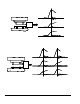
200 TONS TOTAL SLIDE t1 UPPER DIE 100 TONS Punches hit at the same time LEFT CHANNEL BOLSTER t1 100 TONS RIGHT t1 CHANNEL Figure 1: Example Die 1 with Signature When forces occur on the individual channels at different positions in the stroke (at different times), the total force depends on the amount of force exerted at any specific position.
machine frame was 60 tons, that the maximum tonnage measured on the right side of the machine frame was 60 tons, and that the maximum total tonnage exerted on the machine frame was 100 tons. 2.1.3 Reverse Tonnage In addition to monitoring the “forward” tonnages for a press, the tonnage monitor also measures and monitors the “reverse” tonnage. A press frame acts as a kind of stiff spring.
2.2.1 Data Window Start Angle The Start Angle for a data window is the angle at which the setpoints for that data window start to be enforced. For example, in Figure 3 data window 1 has a start angle of 165 degrees. 2.2.2 Data Window End Angle The End Angle for a data window is the angle at which the setpoints for that data window stop being enforced. For example, in Figure 3 data window 1 has an end angle of 170 degrees. 2.
2.3.4 Reverse Limits A Reverse Limit should be set more negative than the maximum reverse tonnage developed when properly producing a particular part and is set for each channel of the tonnage monitor for the peak tonnage only. Data windows do NOT have reverse limits associated with them. If something in the process changes during normal operation that causes the tonnage developed to exceed this maximum reverse limit, a Top Stop is issued.
that the press will not be able to stop before 170 degrees, it will issue a “Top Stop” to minimize the chance of sticking the slide, since the press was going to go through the bottom anyway. Doc #: L-802-1110 Page 12 Rev.
3 OPERATION 3.1 Main Operator Terminal Screen The operator terminal main screen shown in Figure 4 provides the current status of the tonnage monitor module directly beside the TONNAGE MONITOR softkey and indicates if attention is required by the module. 0 0 Drive Speed Stroke Mode TOP Single Stroke 0 0 Stroke Speed SPM Counter OFF Order Counter Current Status SPM Program/Run Switch MAIN SCREEN Job Num.
3.2 The Tonnage Monitor Main Screen The TONNAGE MONITOR softkey in the Main Menu provides access to the tonnage monitor module. This screen shows the maximum forward tonnages recorded during the last stroke, the description and status of each channel, the overall status of the tonnage monitor module, and limits that apply to the current view. Peak forward tonnage, peak reverse tonnage, and data window forward tonnages can be selected for viewing.
In Figure 5, the various parts of the screen are: a) Module Status The overall status of the tonnage monitor. b) Channel Status Each channel also has a status that indicates any alarms conditions or other problems related to just that channel. c) Low Limit Value The low tonnage limit setting for this channel and view (peak, data window 1, data window 2, etc).
CHANGE VIEW Softkey This softkey is used to change the tonnage view between peak, data window 1, data window 2, data window 3, and data window 4 as explained in section 3.2.1 on page 18. LOW LIMITS ON/OFF Softkey This softkey toggles the low limits between ON and OFF. See section 3.2.2 on page 19 for more information on limits. BYPASS ON/OFF Softkey This softkey turns the tonnage monitor bypass mode ON and OFF. See section 3.2.4 on page 22 for more information on bypassing the tonnage monitor.
Figure 6 shows a four channel screen when viewing data window 1 tonnages. Notice that the major difference between this screen and that of Figure 5 is the addition of three new parameters and the lack of a REVERSE TONNAGE softkey. k 0 TOP lm 0 Drive Speed Stroke Mode CH1 - Left Rear High Limit: Stroke Speed Single Stroke View Data Win 1 (ON) Forward Tonnage 39.5 Tons HIGH 150% LOW CH3 - Left Front 0% HIGH 150% Program/Run Switch 11.4 Tons Tonnage Monitor 8.5 LOW CH4 – Right Front 14.
Figure 7 shows a four channel screen when viewing reverse tonnages. Notice that there are no limit bars when viewing reverse tonnage as there is only one reverse limit for each channel. n 0 0 Drive Speed Stroke Mode TOP Stroke Speed Single Stroke View Peak Reverse Tonnage SPM Order Counter OFF Counter Current Status SPM Program/Run Switch Total Tonnage Monitor 7.3 Tons CH1 - Left Rear Rev Limit: - 2.4 150% Status OK CH3 - Left Front 2.0 0% 150% 1.5 Tons Rev Limit: - 2.
window 3 forward, and data window 4 forward. The default view on entering the screen is peak forward tonnages and settings. 3.2.1.1 Viewing the Peak and Data Window Tonnages and Settings The CHANGE VIEW softkey allows the operator to select which set of tonnages and settings are shown on the tonnage monitor screen.
3.2.2.2 Setting Low Limits To set a low limit, first choose the view and channel to change. Place the data entry cursor on a low limit setpoint (see “c” in Figure 5) using the up, down, left, and right arrow keys. Softkey 1 (The uppermost vertical softkey) should read CHANGE LOW LIMIT. Press this softkey to enter numeric entry mode (or simply start entering numbers after the field is selected). Enter the new limit with the numeric keypad and press the ENT key to set the limit.
procedure can be aborted at any time before the sixteenth stroke by pressing this softkey. The previously entered limits will then remain in effect. 3.2.2.5 Turning Low Limits ON or OFF Pressing the LOW LIMITS ON/OFF softkey will toggle all low limits (including those in all data windows) ON or OFF. This key is only available when viewing forward tonnage (as in Figure 5 and Figure 6). Like changing setpoints, this is a restricted operation.
3.2.3.3 Setting the Data Window “End Angle” The “End Angle” for the data window is the crankshaft angle at which the setpoints associated with the window stop being enforced. To change the end angle, change the view to the data window desired. The screen should look something like Figure 6. Place the data entry cursor on the “End Ang” parameter (“m” in Figure 6). Softkey 1 (The uppermost vertical softkey) should read CHANGE END ANGLE.
3.2.5.1 Low Alarm One of the messages listed below in the Channel Status indicates that the maximum tonnage recorded during the last stroke did not reach the Low Limit setting. “Low Peak Alarm” “Low Dw1 Alarm” “Low Dw2 Alarm” “Low Dw3 Alarm” “Low Dw4 Alarm” Tonnage did not reach the Low Limit set in Peak Tonnage. Tonnage did not reach the Low Limit set in Data Window #1. Tonnage did not reach the Low Limit set in Data Window #2. Tonnage did not reach the Low Limit set in Data Window #3.
3.2.5.5 Reverse Rating Alarm A Channel Status message "Reverse Rating" indicates that the maximum reverse tonnage recorded during the last stroke exceeded the reverse channel rating as set by the “Max Reverse Setpoint Level” (see section 4.4.5 on page 45 for details). When this condition is detected on any channel, a Top Stop is issued. 3.2.5.
“Boot Program Corrupt” The boot program failed its’ validity check. If this is not cleared by turning the unit off and back on, then the unit needs to be sent to Link for repair. “Boot Version Mismatch” The boot information block reported a different version for the boot program than reported by the boot program itself. If this is not cleared by turning the unit off and back on, then the unit needs to be sent to Link for repair. “Main Program Corrupt” The main program failed its’ validity check.
“Setpoint Error” The module has detected one or more invalid setpoints (high limit less than low limit, limits higher than machine rating, etc). One likely cause for this error is a change to the machine rating or a change in the “Max Forward Setpoint Level”. Changing either of these settings can result in limits that exceed the new maximum allowed by the settings.
3.3 The Tonnage Monitor Diagnostic Screen Pressing the DIAGNOS softkey in the main tonnage monitor screen will bring up the diagnostic screen shown in Figure 8. 0 TOP 0 Stroke Mode Drive Speed Single Stroke 0 0 Stroke Speed SPM Order Counter OFF Counter Current Status SPM Program/Run Switch Tonnage Monitor Diagnostics VRef Voltage: VRef Current: Tonnage Monitor 10.
Reverse Machine Rating Alarms The number of reverse machine rating alarms that have occurred since the last time the alarm counters were reset. Total Torque Limit Alarms The number of total torque limit alarms that have occurred since the last time the alarm counters were reset. High Limit Alarms The number of high limit alarms that have occurred since the last time the alarm counters were reset.
3.4 The Tonnage Monitor Bypass Setup Screen Pressing the BYPASS SETUP softkey in the main tonnage monitor screen will bring up the screen shown in Figure 9.
3.5 The Tonnage Monitor Graph Screen The GRAPH softkey in the main tonnage monitor screen provides the operator or die setter more detailed analysis of machine forces by displaying tonnage signatures. Figure 10 shows an example screen viewing peak tonnage information, Figure 11 shows the same screen when viewing “data window 2” information, and Figure 12 shows the screen when in Pan/Zoom mode. Notice that the shaded softkeys in these figures change depending on the circumstances.
c) Reverse Limit Bar This line (in red) graphically shows where the reverse limit is set with respect to the tonnage waveform. For a “good” hit, no part of the tonnage waveform should extend below this line. The “R” to the right of the line is for “Reverse”. d) Tonnage Waveform This is the actual tonnage waveform collected by the tonnage monitor. The xaxis is crankshaft angle (or time, depending on the mode) with 180 degrees being bottom dead center.
k) Number of Points The tonnage monitor module indicates the number of sample points taken during the last stroke in the upper right hand part of the screen (“Cap Pts”). This number will depend upon the speed of the press, size of the working portion of the stroke, and the sample rate at which the module is acquiring data. The maximum number of sample points is 4096.
SEND GRAPH Softkey This softkey allows the user to send the tonnage graph to a laptop, the LinkNet network, or to a reference graph depending on the configuration of the system. See section 3.5.6 on page 37 for details. SHOW REF GRAPH / HIDE REF GRAPH Softkey If a reference graph has been stored for the job, this softkey will appear and toggles the display of the reference graph on the screen. GRAPH SETTINGS Softkey This softkey brings up the tonnage monitor graph settings screen. See section 3.
In Figure 11, some additional or different items on data window views are: n) Data Window Bars The lower portion of the graph display is used to indicate the active area of the data windows. This graphically shows the position of the data window with respect to the tonnage waveform. No bar appears for Peak Tonnage since it is always active.
Figure 12 shows an example of a graph screen in Pan/Zoom Mode. This mode allows easy zooming and panning of the waveform on the screen. Use the arrow keys to pan the graph. Press the “CANCEL PAN ZOOM MODE” key to return to normal mode. 100.0 90.0 80.0 70.0 60.0 50.0 40.0 30.0 20.0 10.0 0.0 -10.0 -20.0 -30.0 -40.0 -50.0 Cap Pts: 3143 View Pts: 1085 CHANNEL 1 TONS - PEAK SETPOINTS H L Start 160° End 200° Channel 1 Tonnage NEXT CHANNEL PEAK INFO R 160.0° 180.0° LO LIM 82.3 200.
ZOOM IN HORIZONTAL Softkey This softkey zooms in on the angle or time axis, depending on the x-axis mode. ZOOM OUT HORIZONTAL Softkey This softkey zooms out on the angle or time axis, depending on the x-axis mode. 3.5.1 Graph Start Angle The graph start angle (the number directly under “_Start_” in the example graphs) specifies the crankshaft angle at which to begin displaying the tonnage waveform. This should not be confused with the start angle of a data window.
tonnage on the graph is set just above the highest tonnage of the signature. This should work the vast majority of the time to fill the screen with the actual working portion of the tonnage signature. If for any reason it does not, however, the graph can always be adjusted by hand. 3.5.
Store As Reference The OmniLink II OIT can store one “reference” tonnage waveform per job. This reference waveform can be overlaid with the current waveform to make a direct on-screen comparison of the two. The “Store As Reference” selection of the SEND GRAPH softkey will retrieve the tonnage waveform from the tonnage monitor, make a reference waveform from it, and store it under the current job number.
Print To Network 3.5.7 This option is only available if the LinkNet interface has been set up in auxiliary communications and the network is “online”. When the “Print To Network” option of the SEND GRAPH softkey is selected, the OmniLink will retrieve the tonnage waveform from the tonnage monitor and transfer it to the network host computer. This will result in the tonnage waveform being automatically printed at the configured printer from the LinkNet host computer.
3.6 The Tonnage Monitor Graph Settings Screen The screen of Figure 13 comes up when the GRAPH SETTINGS softkey in the graph screen is pressed. The settings in this screen are not often used, and can usually be left at the default values. However, in cases where the press slows down or stops at the bottom of the stroke, these will need to be set appropriately in order to get a usable graph. The tonnage monitor stores as many as 4096 points per channel when capturing tonnage signatures.
Graph Acquisition Press Speed For normal operation, set this value to 0. For presses that slow or stop at the bottom of the stroke, set this somewhat slower than the actual press speed. It may require some trial and error to find the right value. If the waveform runs out of points (4096 points shown on the graph screen), then lower this value. If the number of points captures is less than 2000, then raise this value. The ideal setting would result in just short of 4096 captured points.
4 CONFIGURATION 4.1 Turning the Tonnage Monitor ON in Device Config Before anything can be configured on the tonnage monitor, the operator terminal must be made aware that it is connected and how many channels will be used. To do this, press the ACC key on the keypad to bring up the “Quick Access” screen. With the RUN/PROG key in the PROG position, the lower left hand softkey should show as DEVICE CONFIG.
0 TOP 0 Stroke Mode Drive Speed Stroke Speed Single Stroke 0 0 Tonnage Monitor Device Configuration Tonnage Monitor Channels: 4 SPM Order Counter OFF Counter Current Status SPM Program/Run Switch Tonnage Monitor CHANGE SETTING EXIT Figure 15: Tonnage Monitor Device Configuration Screen Use the CHANGE SETTING key to select the number of channels for the tonnage monitor.
4.4 The Tonnage Monitor Machine Settings Screen Press the SELECT key to the right of the “Tonnage Monitor Machine Settings” in the Tonnage Monitor Configuration screen as shown in Figure 16 to display the screen shown in Figure 17.
4.4.2 Machine Rating The Machine Rating is the total capacity of the machine frame as defined by the press manufacturer and is typically specified at some position off the bottom of the stroke. The tonnage monitor will use this parameter along with the number of channels to determine the rating of each channel. The scale factors calculated are used to translate strain gage outputs into tonnage values.
of the working portion of the stroke, it should be set prior to the angle that tooling forces begin. The angle can not be less than 45 degrees. The default is 100 degrees. 4.4.9 Sample Window End Angle This angle defines the point in the up portion of the stroke where the tonnage monitor stops sampling the peak tonnage. Alarm counters are updated at this time. Since this angle defines the end of the working portion of the stroke it should be set beyond the angle where tooling forces end.
violates the low limits. When this setting is “Yes”, the tonnage monitor will automatically bypass the low limits while in a setup mode. This happens with no operator intervention and clears itself when going back to a production mode. While in setup mode, the low limits are clearly indicated as off in each channel status line with “Setup Mode Low Lim OFF” displayed in yellow.
4.6 The Machine Rating De-rate Table Screen Press the SELECT key to the right of the “Tonnage Monitor Calibration” in the Tonnage Monitor Configuration screen as shown in Figure 16 to display the screen shown in Figure 20. A mechanical power press is typically specified by its manufacturer with a tonnage capacity rating and a height off of the bottom of the stroke at which this rating applies.
Figure 20 shows the table of 16 angle regions and % of machine rating for that angle region approximated from the curve. The screen shows that a Total Alarm will occur if tonnage exceeds 35% of machine rating from 90 degrees to 114 degrees, 40% from 115 to 123 degrees, etc. This feature is not required and may be bypassed by leaving 125% for all tonnage limits or 0 degrees for each angle that is not used.
5 JOB SETUPS In the Link operator terminal, all pertinent information for the current job such as programmable limit switch setpoints, automatic feed settings, and tonnage monitor limits can be stored for later use as a block of information called a "job setup". Since this programmed data may change from job to job or as machine dies are changed, saving a job setup prevents the operator from having to manually change all this information when dies are changed.
6 INSTALLATION The Tonnage and Analog Signal Monitor module can be used with the OmniLink II Press Automation Control system or with the OmniLink 5000 Press Control system. In both cases, the unit is tied to the control system with a high speed serial bus. 6.1 Mounting the Module The Tonnage and Analog Signal Monitor module can be mounted in the press control enclosure or in its own enclosure. If the unit is to be mounted in a location subject to shock and vibration, shock mounts are required.
6.2 Faceplate Connections and Indicators The faceplate of the Tonnage and 5100-8A Option Connector Analog Signal module is labeled for = Common COM TONNAGE & ANALOG the connectors that provide for field O5 to O8 = Outputs 5 to 8 SIGNAL MONITOR I5A, I5B = Input 5 connection of devices and wiring back R R = 24 Volts DC Output +24V C + + C to the OmniLink controller.
speed serial cable, the power cable does not have to be “daisy-chained”. Power can be taken from any convenient source. The power wiring should be at least 16 GA. WARNING! While the Tonnage & Analog Signal Monitor (and most newer Link products) has a “universal power supply” and can operate from 88-264VAC, some older modules operate on 110VAC only.
NOTE: Always use the cable specified by Link Systems for the high speed serial bus! This cable has been chosen to optimize communication speed and distance for the serial bus. Use of any other cable may result in communication faults that cause nuisance stops of your press production system. DO NOT splice cable sections between modules. Use only unbroken runs of cable between modules.
A simple method of determining if the Tonnage Monitor is at the end of the bus is to check the high speed bus connector. If only one cable is wired into this connector, then the unit is at the end of the bus. If two cables are wired into the connector, then the unit is not at the end of the bus and termination should not be made active. 6.6 Strain Gage Locations 6.6.
The best strain gage locations are below gibs and at least 12 inches above where the upright joins the machine bed. Locating the strain gage in the gib region can cause excessive bending moments to be translated through the gibs into the upright as the slide tries to "cock" for some conditions of off-center loading. Locations too near the bottom of the upright may produce a non-uniform strain field. Do not mount strain gages on any side of an upright that has a tie rod access opening.
On solid frame straight side machines, the preferred strain gage mounting location is inside the "windows" under the ends of the crankshaft. A strain gage should be mounted on the inside face of each column forming the "windows" as shown in Figure 31. Crankshaft End Strain Links Figure 31: Solid Frame Machine Gage Locations 6.7 Strain Gage Mounting Strain gages may be bolted directly to the machine or bolted to intermediate pads welded or adhered to the machine. 6.7.
4) Place the hardened drill fixture provided with the direct mounting strain gage kit in position adjacent to the scribed line. Use a number 3 drill to drill a 5/8" deep hole in the mounting surface through the center hole position of the drill fixture. Tap the hole for a 1/4 x 28 thread. Bolt the drill fixture securely to the mounting area, as shown in Figure 32. Drill Fixture 5) Use a number 3 drill to drill 5/8” deep holes in the mounting surface through the remaining four holes in the drill fixture.
4) Assemble the intermediate pads to the alignment/clamping fixture using the 1/4 x 28 bolts provided, as shown in Figure 34. Weld Pad Fixture 5) Hold the alignment/clamping fixture firmly on the mounting area in the direction of tension or compression of the structural member or, alternatively, drill a 5/8" deep hole through the center hole of the alignment/clamping fixture, tap for 1/4 x 28 threads, and bolt the alignment/clamping fixture to the mounting area through the center hole.
much as possible. Run cables to the channel connectors on the front of the tonnage monitor module and cut the excess cable lengths off. 3) Strip about 2 ½ inches of cable insulation off of the braided wire shield. Remove the four conductor wires from the shield, taking care to leave the shield wire length connected to the cable. 4) Wire the channel connectors as shown in Figure 36. Cover or tape the shield, to avoid accidental shorting to any other point.
6.9 Installation Procedure 1) Position the press at the top of the stroke, turn power to the machine off, and install tonnage monitor card in the enclosure. Make certain both knurled screws that hold the module in place are tight (see section 6.1 on page 51). NOTE: If this installation is replacing a System 1000, System 1100, or System 5000 tonnage monitor already installed on the machine, then write down the present machine rating and cal. numbers before turning power OFF.
10) Exit back to the Tonnage Monitor Screen and enter high limits and low limits (for Peak Tonnage and all Data Windows). Enter reverse limits. Alternatively, run an auto-setup to have the tonnage monitor set the limits for you. Doc #: L-802-1110 Page 62 Rev.
7 CALIBRATION Calibration of the tonnage monitor consists of achieving a known load on the machine and adjusting the installed monitor so that the known load is displayed correctly. The known load used during calibration should be at least 50% of rated machine load and preferably 100% of rated machine load.
WARNING: Extreme care should be used in calibration procedures for tonnage monitors. Severe damage to the machine being calibrated or the calibration equipment can result from incorrect shut height adjustments. Injury to personnel calibrating the machine or to others in the machine area can result from poorly implemented load cell or hydraulic jack stacks that fly out of the machine under load.
cells as necessary to reduce the gap between slide and bolster so that the "stack" of load cells and parallels can be contacted at the bottom of the machine stroke. It is recommended that steel plates at least one inch thick and of at least 2 inches greater lateral dimension than the load cell contact surfaces be placed both under and over the load cell to help distribute the load and avoid load cell impressions in the slide or bolster material.
When load cell tonnages are equalized, again repeat the cycle of single stroking the machine with shut height or other bottom of stroke adjustment between strokes and continue to observe the tonnage on each load cell. It may be necessary to re-shim certain load cell stacks to equalize tonnage on all load cells as rated tonnage capacity of the machine is neared.
16) Reduce the load gradually, and verify that the tonnages displayed by the tonnage monitor "track" within one or two percent of those of displayed on the load cells. Failure of this indicates a non-linearity which could be due to incorrect strain gauge location, improper strain gauge mounting, or incorrect tie rod tension (in frames of this construction). 17) Press the EXIT softkey and return to the tonnage monitor menu. 18) Remove the load cells and associated "stack" elements from the machine.
equal loads are on the load cells. If the channels with much higher calibration numbers now give tonnage readings much larger than the channels with lower calibration numbers improper tie rod tension is indicated. Another way to check for loose tie rods is to check the tonnage graph when hitting load cells at near machine rating. Figure 38 shows a tonnage graph of a typical load cell hit on a machine with tie rods that are in proper tension. There is a characteristic “hump” shape with a rounded top.
8 OPTIONAL COMPONENTS The 5100-8 Tonnage & Analog Signal Monitor has some optional components available to add features and capabilities to the base system. Figure 39 shows the main circuit board of the tonnage monitor. There are connectors and standoffs on this board used for mounting the options described in the following sections.
One opto-isolated input is also provided to allow triggering measurements not associated with the crank position. For instance, a PLC could trigger a measurement based on some condition external to the press. Figure 40 shows how the 5100-8A option mounts to the main circuit board. The board to board connectors (see the “5100-8A Option Connector” in Figure 39) must be aligned when the boards are mated. Four 6-32 screws with lock washers secure the option board to the main board.
8.2 The 5100-8C Die Protection and Programmable Limit Switch Option The 5100-8C option add four die protection channels and 4 programmable limits switch outputs to the base tonnage monitor. The tonnage monitor will detect the presence of the option board and automatically enable the appropriate functionality. Figure 41 shows how the 5100-8C option mounts to the main circuit board. The board to board connectors (see the “5100-8C Option Connector” in Figure 39) must be aligned when the boards are mated.
or PNP on a channel by channel basis and provide powerful die protection functions. Refer to the Die Protection manual for details on operation. NOTE: The +24V pin on the 5100-8C option connector may be used to power die protection sensors as well as the relay output board described below. Draw no more than 0.8 amps from the +24V pin for this purpose. In the vast majority of cases this will be more than enough current to power four sensors.
Figure 43 shows the necessary connections between the tonnage monitor and the relay board. 5100-8C Option Connector Relay 1 Fuse 1 Fuse 3 Fuse 4 CON9 1 2 3 4 5 Fuse 2 CON10 1 2 3 4 5 6 7 8 Relay 2 Relay 3 Relay 4 802-5B Connections 802-5 CON9 1 2 3 4 5 Ton. Mon.
9 TROUBLESHOOTING Most of the errors generated by the tonnage monitor are straightforward and are adequately covered in sections 3.2.6 (Error Conditions) on page 24. However, some of these conditions are a little more involved and bear further discussion. Link is also happy to assist in diagnosis and troubleshooting of its equipment and can be reached at (615) 833-4168. 9.
9.1.1 “Communication Failure” If the tonnage monitor is reporting “Communication Failure” in “Module Status” at the bottom of the tonnage monitor main screen, then the following process should be followed: 1) First, check to see if any other option modules, such as die protection or limit switch, are also reporting “Communication Failure”. Note that you have to be a little careful when checking for this. If the 5100-8C option is installed in the tonnage monitor (see section 8.
4) If no wires are loose, check the high speed bus cable for damage to the outer jacket. If no damage is found, then flex and bend the high speed bus cable section by section while checking to see if the error returns. This should find most damaged cables with internal intermittently open wires. Replace the entire section of cable if this is found. 5) Wiggle the high speed serial bus connector on the tonnage monitor module. If the error reappears while doing this then the connector is likely damaged. 9.1.
10 PART TRACKING The System 5000 Press Control and the OmniLink II Automation Control have the ability to track the status of parts (good, bad, or empty) traveling through stations of the die. Up to 12 strips of 32 stations each can be monitored. Part tracking enables new capabilities for the system as a whole. Analog Signal Monitor channels and Die Protection channels can mark parts as bad or empty.
11 PARAMETER ENTRY AND ACCESS CONTROL 11.1 Parameter Entry Throughout the OmniLink control, a fairly standard form of data entry is employed. When data entry is allowed, an “editing cursor” will appear on the screen. This cursor can typically be moved from parameter to parameter on the screen with the up, down, left, and right arrow keys. The topmost softkey is used to select the parameter for editing and can change description depending on the parameter selected. 11.1.
4) Use the left and right arrow keys to point to the letter desired in the letter box next to the text being edited. This box will appear just above or just below the text to be edited depending on where it is on the screen. Hit the SELECT LETTER softkey to place that letter at the text cursor. In Figure 44, the text cursor is on the “T” in “This” and would be replaced with an “A”. The text cursor will automatically move to the right when a letter is selected.
11.3 Access Control Modes The OmniLink control has many parameters or operations where access may need to be restricted to certain personnel. Common examples include resetting faults, changing limit settings, and bypassing modules. The OmniLink control provides several means to limit access to these parameters or operations. These parameters and operations are called restricted items. The OmniLink control uses combinations of two different methods to limit access to restricted items.
The example above can be taken one additional step if two press operators are given different user names and different passwords. One operator can be assigned the ability to change tonnage monitor limits in addition to the ability to reset faults, while the other operator is not assigned the ability to change the limits. 11.3.3 Password Only Mode The “Password Only” mode allows for sixteen users. Each user can be assigned access to some or all of the restricted items.
11.4.2 Password System Operation Figure 45 displays an example password entry sequence. This example shows the steps necessary to change a tonnage monitor setpoint but is typical for password entry for all restricted items. Step 1: Select the restricted item. In the example the restricted item is the channel 2 high limit. Once the parameter is selected, Softkey 1 will display the legend SUPPLY ACCESS CODE. 0 0 SPM Order Counter Tonnage Monitor Press Supply Access Code Key High Limit: 25.
In addition to the manual log out, the system contains an automatic logout function. The intent of automatic log out is to reduce the possibility of users other than the intended user having access to restricted items. If there were no provisions for automatic log out and a user forgot to manually log out, all restricted items to which the user had been designated for access would be available from the log in time until power was removed from the OmniLink control.
The following table lists the different items and functions in the tonnage monitor that can be configured to be completely unrestricted. Once unrestricted, no RUN/PROG key or code will be necessary to change the item or perform the function. Tonnage Monitor Unrestricted Items/Functions Name TM Reset Doc #: L-802-1110 Function Reset tonnage monitor faults. Page 84 Rev.