
User Manual


Doc #: L-802-1110 Page 58 Rev. 02
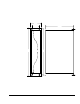
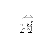
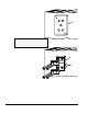
4) Place the hardened drill fixture provided with
the direct mounting strain gage kit in position
adjacent to the scribed line. Use a num ber 3
drill to drill a 5/8" deep hole in the mounting
surface through the center hole position of the
drill fixture. Tap the hole for a 1/4 x 28 thread.
Bolt the drill fixture securely to the mounting
area, as shown in Figure 32.
Drill
Fixture
Drill
Fixture
5) Use a number 3 drill to drill 5/8” deep holes in
the mounting surface through the remaining
four holes in the drill fixture. Tap the holes for
a 1/4 x 28 thread after removing the drill
fixture.
NOTE: Do not attempt to locate and drill
mounting holes without using the
drill fixture. The hole pattern
Figure 32: Strain Gage Drill Fixture
must be precise.
6) De-burr the mounting holes and wipe the
mounting area with a clean rag.
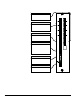
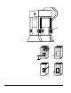
7) Mount the strain gage as shown in Figure
33. Make certain that the washers provided
with the strain gage kit are placed over the
strain gages, not under them. Torque the
1/4 x 28 bolts to 150 in-lbs. A calibrated
torque wrench is the preferred tool to torque
the bolts.
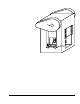
8) Mount the protective cover box provided in
the strain gage kit, if used, centrally over the
strain gage. It is important to mount the
cover box before calibration begins. The
cover box mounting holes may slightly
change the strain sensed by the strain gage.
LST-1000
Strain Gage
6.7.2 Intermediate Weld Pad Mounting
1) Select the desired mounting locations for the strain gages.
2) Remove paint, oil, grease, etc., to obtain a bare metal surface slightly larger than the LST-1000
strain gage.
3) Clean the mounting surface with a solvent, removing all contam inants.
Washers
LST-1000
Strain Gage
Washers
Figure 33: LST-1000 Strain Gage Mounting