USER GUIDE BUSINESS SERIES Business Series Smart Gigabit Ethernet Switch Model: SLM2048, SLM2024, SLM248G, SLM248P, SLM224G, SLM224P
About This Guide About This Guide Icon Descriptions While reading through the User Guide you may encounter various icons designed to call attention to a specific item. Below is a description of these icons: NOTE: This check mark indicates that there is a note of interest and is something that you should pay special attention to while using the product. WARNING: This exclamation point indicates that there is a caution or warning and it is something that could damage your property or product.
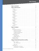
Table of Contents Chapter 1: Introduction 1 Chapter 2: Product Overview 2 SLM2048 . . . . . . . . . . . . . . . . . . . . . . . . . . . . . . . . . . . . . . . . . . . . . . . . . . . . 2 Front Panel . . . . . . . . . . . . . . . . . . . . . . . . . . . . . . . . . . . . . . . . . . . . . . . 2 Back Panel . . . . . . . . . . . . . . . . . . . . . . . . . . . . . . . . . .
Table of Contents Port Management > LACP . . . . . . . . . . . . . . . . . . . . . . . . . . . . . . . . . . . . . 17 Port Management > PoE Power Settings . . . . . . . . . . . . . . . . . . . . . . . . . . . . 17 VLAN Management . . . . . . . . . . . . . . . . . . . . . . . . . . . . . . . . . . . . . . . . . . . . 18 VLAN Management > Create VLAN . . . . . . . . . . . . . . . . . .
Table of Contents Fiber Optic Cabling . . . . . . . . . . . . . . . . . . . . . . . . . . . . . . . . . . . . . . . . . . . . 37 Appendix B: Glossary 38 Appendix C: Specifications 42 SLM2024/SLM2048 . . . . . . . . . . . . . . . . . . . . . . . . . . . . . . . . . . . . . . . . . . . . 42 SLM224G/SLM248G/SLM224P/SLM248P . . . . . . . . . . . . . . . . . . . . . . . . . . . . . .
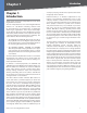
Chapter 1 Chapter 1: Introduction Thank you for choosing the Linksys Business Series Smart Gigabit Ethernet Switch. The new Linksys Business Series Smart Gigabit Ethernet Switches are cost-effective switching solutions ideal for small businesses, the network edge, or workgroups within larger organizations. These easy-to-install, highspeed switches offer many of the same Quality of Service and Security features found in more expensive full Layer 2 managed switches but without their complexity.
Chapter 2 Chapter 2: Product Overview SLM2048 Front Panel Product Overview miniGBIC (1-2) The miniGBIC (gigabit interface converter) port is a connection point for a miniGBIC expansion module, so the Switch can be uplinked via fiber to another switch. The MiniGBIC port provides a link to a high-speed network segment or individual workstation at speeds of up to 1000 Mbps. The Switch’s LEDs and ports are located on the front panel.
Chapter 2 SLM2024 Front Panel The Switch’s LEDs and ports are located on the front panel. Front Panel of the SLM2024 SYSTEM (Green) Lights up to indicate that the Switch is powered on. Blinks while the Switch is performing a system self-test. LNK/ACT (1-24) (Green) Lights up to indicate a functional 10/100/1000 Mbps network link through the corresponding port (1 through 24) with an attached device. Blinks to indicate that the Switch is actively sending or receiving data over that port.
Chapter 2 SLM248G Front Panel The Switch’s LEDs and ports are located on the front panel. Front Panel of the SLM248G SYSTEM (Green) Lights up to indicate that the Switch is powered on. Blinks while the Switch is performing a system self-test. LNK/ACT (1-48) (Green) Lights up to indicate a functional 10/100 Mbps network link through the corresponding port (1 through 48) with an attached device. Blinks to indicate that the Switch is actively sending or receiving data over that port.
Chapter 2 SLM248P Front Panel The Switch’s LEDs and ports are located on the front panel. Front Panel of the SLM248P SYSTEM (Green) Lights up to indicate that the Switch is powered on. Blinks while the Switch is performing a system self-test. LNK/ACT (1-48) (Green) Lights up to indicate a functional 10/100 Mbps network link through the corresponding port (1 through 48) with an attached device. Blinks to indicate that the Switch is actively sending or receiving data over that port.
Chapter 2 SLM224G Front Panel The Switch’s LEDs and ports are located on the front panel. Front Panel of the SLM224G SYSTEM (Green) Lights up to indicate that the Switch is powered on. Blinks while the Switch is performing a system self-test. LNK/ACT (1-24) (Green) Lights up to indicate a functional 10/100 Mbps network link through the corresponding port (1 through 24) with an attached device. Blinks to indicate that the Switch is actively sending or receiving data over that port.
Chapter 2 SLM224P Front Panel The Switch’s LEDs and ports are located on the front panel. Front Panel of the SLM224P SYSTEM (Green) Lights up to indicate that the Switch is powered on. Blinks while the Switch is performing a system self-test. LNK/ACT (1-24) (Green) Lights up to indicate a functional 10/100 Mbps network link through the corresponding port (1 through 24) with an attached device. Blinks to indicate that the Switch is actively sending or receiving data over that port.
Chapter 3 Installation Chapter 3: Installation Pre-Installation Considerations Fast Ethernet Considerations If you are using the Switch for Fast Ethernet (100 Mbps) applications, you must observe the following guidelines: Overview This chapter will explain how to connect network devices to the Switch. The following diagram shows a typical network configuration.
Chapter 3 Desktop Placement • Attach the rubber feet to the recessed areas on the bottom of the Switch. • Place the Switch on a desktop near an AC power source. • Keep enough ventilation space for the switch and check the environmental restrictions mentioned in the Specifications Appendix as you are placing the Switch. Installation To rack-mount the Switch in any standard 19-inch wide, 1U high rack, follow the instructions described below. 1.
Chapter 3 For a 1000 Mbps device: Installation Ethernet Ports Shared with miniGBIC Ports • SLM2048 and SLM2024: Connect a Category 5e Ethernet network cable to one of the numbered ports on the Switch. Switch Port Shared with miniGBIC1 Port Shared with miniGBIC2 • SLM248G, SLM248P, SLM224G, SLM224P: Connect SLM2048 24 48 SLM2024 12 24 SLM248G, SLM248P, SLM224G, SLM224P G1 G2 a Category 5e Ethernet network cable to port G1 or port G2 on the Switch.
Chapter 4 Chapter 4: Configuration Using the Web-based Utility This chapter describes the features included in the Webbased Utility. All features shown in this chapter, unless specifically identified, are included in the all of Smart Switches. Unique features for specific Switches are noted. NOTE: The web-based utility is optimized for a screen resolution of 1024 x 768. Internet Explorer version 5.5 or above is recommended.. To use the utility, open your web browser, enter http://192.168.1.
Chapter 4 Device Information System Name Displays the name of the Switch, if one has been entered on the Setup tab’s Network Settings screen. IP Address The IP address assigned to the Switch. The Switch’s default IP address is 192.168.1.254. This setting can be configured from the Setup tab’s Network Settings screen. Subnet Mask The Subnet Mask assigned to the Switch. The default subnet mask is 255.255.255.0. This setting can be configured from the Setup tab’s Network Settings screen.
Chapter 4 Configuration Using the Web-based Utility IP Configuration Setup > Time Management VLAN This drop-down menu allows you to select the Management VLAN. The default value is 1. The Time screen allows you to configure the time settings for the Switch. WARNING: The Management VLAN must be set to 1 (default VLAN) if the system IP address (IP Address field) is set to 192.168.1.254. Otherwise, you may not be able to access the system.
Chapter 4 Configuration Using the Web-based Utility Port Management Flow Control The type of flow control currently in use. The Port Management tab contains the Port Settings, Link Aggregation, and LACP screens. On the SLM224P and SLM248P only, this tab also contains the PoE Power Settings screen. LAG The LAG to which the port belongs, if the port is a LAG member.
Chapter 4 Reactivate Suspended Port If the port has been suspended, select this checkbox to reactivate the port. Operational Status (Read-only) Displays whether the port is operational or non-operational. Admin Speed Use this to manually set the port’s configured transmission rate in Mbps. You can select 10M, 100M, or 1000M (Gigabit ports only). Before you change this setting, make sure that Auto Negotiation is disabled. Current Port Speed (Read-only) The port’s current rate in Mbps.
Chapter 4 Speed Displays the port speed. Duplex Displays the duplex mode. Configuration Using the Web-based Utility Operational Status (Read-only) Displays whether the LAG is operational or non-operational. Detail To create a new LAG, click Detail in the Detail column to display the Link Aggregation detail screen. Admin Auto Negotiation Select Enable (default) or Disable to enable or disable Auto-Negotiation on the LAG.
Chapter 4 Port Management > LACP In addition to LAGs that you create by manually grouping ports together, you can also use the Link Aggregation Control Protocol (LACP) to automatically negotiate a LAG link between the Switch and another network device. The LACP screen contains fields for configuring LACP LAGs. This screen is divided into three parts: Global Parameter, Port Priority, and LACP Port Table.
Chapter 4 Configuration Using the Web-based Utility VLAN Management VLAN Management > Port Settings A VLAN is a group of ports that can be located anywhere in the network, but communicate as though they belong to the same physical segment. The Port Settings screen allows you to configure the ports in a VLAN. VLANs help to simplify network management by allowing you to move devices to a new VLAN without having to change any physical connections.
Chapter 4 Configuration Using the Web-based Utility VLANs Displays the IDs of the VLANs to which the port belongs, prefixed by “T” if the port is tagged or “U” if the port is untagged in that VLAN. LAG Displays the LAG to which the port belongs, if any. If a port belongs to a LAG, it cannot belong to a VLAN. However, the LAG to which the port belongs can be configured to belong to a VLAN.
Chapter 4 Configuration Using the Web-based Utility Statistics • Unicast Packets Displays the number of Unicast The Statistics tab contains the Interface Statistics screen, which lets you display statistics for a specified interface. • Multicast Packets Displays the number of Multicast Statistics > Interface Statistics • Broadcast Packets Displays the number of Broadcast packets transmitted from the selected interface. packets transmitted from the selected interface.
Chapter 4 Security Configuration Using the Web-based Utility Table Security > 802.1x Settings The 802.1x Settings screen is used to configure a port’s 802.1x authentication settings. This part of the 802.1x Settings screen displays a summary of the settings that appear in the Parameters section of the screen. If you click More Details, the settings described in the “Setting Timer” section are added to the table. Click Save Settings to apply the changes, or Cancel Changes to cancel the changes.
Chapter 4 Security > Port Security The Port Security screen is used to configure a port’s security settings. Configuration Using the Web-based Utility Learning Mode Defines the locked port type. This field is enabled only if Lock Interface is not selected. The possible values are: • Classic Lock Locks the port using the classic lock mechanism. The port is immediately locked, regardless of how many addresses have already been learned.
Chapter 4 Configuration Using the Web-based Utility Security > IP Access List Security > Storm Control Use the IP Access List (also known as Management Access List) screen to specify IP addresses that are to be allowed to manage the device, using an IP address and wildcard mask. The Storm Control screen is used to configure broadcast and multicast storm control. Security > Storm Control Security > IP Access List IP Address Enter the IP address to be allowed.
Chapter 4 Security > RADIUS The RADIUS screen is used to configure a Remote Authorization Dial-In User Service (RADIUS) server for user authentication. Configuration Using the Web-based Utility Source IP Address Defines the source IP address that is used for communication with RADIUS servers. Usage Type Specifies the RADIUS server authentication type. The default value is Login. The possible field values are: • Login Indicates that the RADIUS server is used for authenticating user name and passwords.
Chapter 4 QoS Network traffic is usually unpredictable, and the only basic assurance that can be offered is best effort traffic delivery. To overcome this challenge, Quality of Service (QoS) is applied throughout the network. This ensures that network traffic is prioritized according to specified criteria, and that specific traffic receives preferential treatment.
Chapter 4 Configuration Using the Web-based Utility QoS > Queue Settings DSCP Indicates the DSCP value in the incoming packet. Select a DSCP value from the drop-down menu to map that value to the associated queue. You can select the DSCP value for the High, Medium, and Normal priority queues. The DSCP values for the Low priority queue are selected automatically based on the other DSCP values. The Queue Settings screen contains fields for defining the QoS queue forwarding types.
Chapter 4 Spanning Tree Spanning Tree Protocol (STP) provides tree topography for any arrangement of bridges. STP also provides one path between end stations on a network, eliminating loops. Loops occur when alternate routes exist between hosts. Loops in an extended network can cause bridges to forward traffic indefinitely, resulting in increased traffic and reducing network efficiency.
Chapter 4 Long Specifies a range of 1-200,000,000 for port path costs. The default path costs assigned to an interface varies according to the selected method. Bridge Settings Priority Specifies the bridge priority value. When switches or bridges are running STP, each is assigned a priority. After exchanging BPDUs, the device with the lowest priority value becomes the Root Bridge. The default value is 32768. The value must be a multiple of 4096. For example, 4096, 8192, 12288, etc. The range is 0 to 65535.
Chapter 4 Multicast Multicast configuration options include IGMP Snooping, Bridge Multicast, and Bridge Multicast Forward All. Multicast > IGMP Snooping Configuration Using the Web-based Utility Auto Learn Select this option to enable Auto Learn on the device. If Auto Learn is enabled, the device automatically learns where other Multicast groups are located. The default is enabled (option is selected). Host Timeout Indicates the amount of time host waits to receive a message before timing out.
Chapter 4 Configuration Using the Web-based Utility Bridge Multicast Address Identifies the Multicast group MAC address/IP address. Bridge IP Multicast Displays the port that can be added to a Multicast service. Interface, Gigabit, LAG Lists switch interfaces and LAGs that can be added to a Multicast service. The configuration options are as follows: • Static Indicates the port is user-defined. • Dynamic Indicates dynamically.
Chapter 4 Admin The Admin tab provides access to system administration settings and tools. It includes the following screens: Admin > User Authentication The User Authentication screen is used to modify user account information. You can modify the password or user name for an existing account, or create additional accounts. Configuration Using the Web-based Utility Add to List/Update This button changes depending on the function you are performing.
Chapter 4 Admin > Static Address Configuration Using the Web-based Utility Admin > Dynamic Address Admin > Static Address Admin > Dynamic Address The Static Address screen lets you assign a static address to a specific interface on the Switch. A static address is bound to its assigned interface and cannot be moved. If a static address is seen on an interface to which it is not assigned, the address is ignored and is not written to the address table.
Chapter 4 Admin > Port Mirroring Configuration Using the Web-based Utility Admin > Save Configuration Port mirroring monitors and mirrors network traffic by forwarding copies of incoming and outgoing packets from one port to a monitoring port. Port mirroring can be used as diagnostic tool and/or a debugging feature. Port mirroring also enables switch performance monitoring.
Chapter 4 Admin > Firmware Upgrade Configuration Using the Web-based Utility Admin > Reboot The Reboot screen is used to reset the Switch. The current configuration settings are automatically saved before the Switch is rebooted. Admin > Firmware Upgrade The Firmware Upgrade screen allows you to download firmware upgrade files from a TFTP server, or from your computer via the HTTP interface. Via TFTP Select this to download from or upload to a TFTP server.
Chapter 4 Admin > Logging Configuration Using the Web-based Utility Admin > Memory Logs The Memory Log screen contains all system logs in chronological order that are saved in RAM (Cache). Log Index Displays the log number. Log Time Displays the date and time at which the log was generated. Severity Displays the log severity. Description Displays the log message text. Admin > Logging The System Logs allow you to view device events in real time, and recording the events for later usage.
Chapter 4 Configuration Using the Web-based Utility Logout The Logout tab is used to terminate the login session. When you select the Logout tab, the following dialog box asks you to verify if you want to log out. Logout Verification If you select Yes, a confirmation screen appears.
Appendix A About Gigabit Ethernet and Fiber Optic Cabling Appendix A: About Gigabit Ethernet and Fiber Optic Cabling Gigabit Ethernet Gigabit Ethernet runs at speeds of 1Gbps (Gigabit per second), ten times faster than 100Mbps Fast Ethernet, but it still integrates seamlessly with 100Mbps Fast Ethernet hardware. Users can connect Gigabit Ethernet hardware with either fiber optic cabling or copper Category 5e cabling, with fiber optics more suited for network backbones.
Appendix B Glossary Appendix B: Glossary Baud Indicates the number of signaling elements transmitted each second. This glossary contains some basic networking terms you may come across when using this product. Bit A binary digit. WEB: For additional terms, please visit the glossary at www.linksys.com/glossary Access Mode Specifies the method by which user access is granted to the system.
Appendix B CoS (Class of Service) The 802.1p priority scheme. CoS provides a method for tagging packets with priority information. A CoS value between 0-7 is added to the Layer II header of packets, where zero is the lowest priority and seven is the highest. DDNS (Dynamic Domain Name System) Allows the hosting of a website, FTP server, or e-mail server with a fixed domain name (e.g., www.xyz.com) and a dynamic IP address. Default Gateway A device that forwards Internet traffic from your local area network.
Appendix B Glossary MAC (Media Access Control) Address The unique address that a manufacturer assigns to each networking device. RADIUS (Remote Authentication Dial-In User Service) A protocol that uses an authentication server to control network access. Mask A filter that includes or excludes certain values, for example parts of an IP address. RJ-45 (Registered Jack-45) An Ethernet connector that holds up to eight wires.
Appendix B Glossary TCP (Transmission Control Protocol) A network protocol for transmitting data that requires acknowledgement from the recipient of data sent. TCP/IP (Transmission Control Protocol/Internet Protocol) A set of instructions PCs use to communicate over a network. Telnet A user command and TCP/IP protocol used for accessing remote PCs. TFTP (Trivial File Transfer Protocol) A version of the TCP/IP FTP protocol that has no directory or password capability.
Appendix C Specifications Appendix C: Specifications SLM2024/SLM2048 Security 802.1X - RADIUS Authentication. MD5 Encryption Port Security - MAC-based Filtering Management Access Control Specifications Ports 24 or 48 RJ-45 connectors for 10BASE-T/100BASE-TX/1000BASE-T including 2 combo ports with miniGBIC/SFP slots Auto MDI/MDI-X Auto-negotiate/Manual setting Availability Link Aggregation Link Aggregation using IEEE 802.
Appendix C Specifications Power Internal Power, 100-240V Management Certification FCC Part15 Class A, CE Class A, UL, cUL, CE mark, CB Web User Interface Built-in Web UI for easy browserbased configuration (HTTP) Operating Temp. 32 to 122ºF (0 to 50ºC) Firmware Upgrade Storage Temp.
Appendix C Specifications Environmental Dimensions (W x H x D) SLM224G, SLM224P, SLM248G: 17.32" x 1.70" x 10.12” (440 x 43 x 257 mm) SLM248G: 17.32" x 1.70" x 13.58” (440 x 43 x 345 mm) Unit Weight SLM224G: 6.39 lb (2.9 kg) SLM248G: 6.83 lb (3.1 kg) SLM224P: 7.28 lb (3.3 kg) SLM248P: 10.14 lb (4.6 kg) Power Internal Power, 100-240V Certification FCC Part15 Class A, CE Class A, UL, cUL, CE mark, CB Operating Temp. 32 to 122ºF (0 to 50ºC) Storage Temp.
Appendix D Appendix D: Warranty Information Limited Warranty Linksys warrants to You that, for a period of five years (the "Warranty Period"), your Linksys Product will be substantially free of defects in materials and workmanship under normal use. Your exclusive remedy and Linksys’ entire liability under this warranty will be for Linksys at its option to repair or replace the Product or refund Your purchase price less any rebates. This limited warranty extends only to the original purchaser.
Appendix E Appendix E: Regulatory Information FCC Statement This equipment has been tested and complies with the specifications for a Class A digital device, pursuant to Part 15 of the FCC Rules. Operation is subject to the following two conditions: (1) this device may not cause harmful interference, and (2) this device must accept any interference received, including interference that may cause undesired operation.
Appendix E User Information for Consumer Products Covered by EU Directive 2002/96/EC on Waste Electric and Electronic Equipment (WEEE) This document contains important information for users with regards to the proper disposal and recycling of Linksys products.
Appendix E Regulatory Information Eesti (Estonian) - Keskkonnaalane informatsioon Euroopa Liidus asuvatele klientidele Français (French) - Informations environnementales pour les clients de l’Union européenne Euroopa Liidu direktiivi 2002/96/EÜ nõuete kohaselt on seadmeid, millel on tootel või pakendil käesolev sümbol , keelatud kõrvaldada koos sorteerimata olmejäätmetega. See sümbol näitab, et toode tuleks kõrvaldada eraldi tavalistest olmejäätmevoogudest.
Appendix E Regulatory Information Lietuvškai (Lithuanian) - Aplinkosaugos informacija, skirta Europos Sąjungos vartotojams Nederlands (Dutch) - Milieu-informatie voor klanten in de Europese Unie Europos direktyva 2002/96/EC numato, kad įrangos, kuri ir kurios pakuotė yra pažymėta šiuo simboliu (įveskite simbolį), negalima šalinti kartu su nerūšiuotomis komunalinėmis atliekomis. Šis simbolis rodo, kad gaminį reikia šalinti atskirai nuo bendro buitinių atliekų srauto.
Appendix E Regulatory Information Português (Portuguese) - Informação ambiental para clientes da União Europeia Slovenčina (Slovene) - Okoljske informacije za stranke v Evropski uniji A Directiva Europeia 2002/96/CE exige que o equipamento que exibe este símbolo no produto e/ou na sua embalagem não seja eliminado junto com os resíduos municipais não separados. O símbolo indica que este produto deve ser eliminado separadamente dos resíduos domésticos regulares.
Appendix E Contact Information Appendix E: Contact Information Linksys Contact Information Website http://www.linksys.com FTP Site ftp.linksys.com Advice Line 800-546-5797 (LINKSYS) Support 800-326-7114 RMA (Return Merchandise 949-823-3000 Authorization) Fax 949-823-3002 NOTE: Details on warranty and RMA issues can be found in the Warranty and Regulatory Information section of this Guide.