User Guide Wireless Access Point With Cloud Manager LAPAC1200C / LAPAC1750C 1
Contents Package Contents .................................................................................................. 4 Device Features ....................................................................................................................................... 4 Mounting Guide ........................................................................................................................................ 5 Access Point Setup Guide ...................................................
Appendix C - PC and Server Configuration ............................................. 118 Overview ............................................................................................................................................... 118 Using WEP ............................................................................................................................................ 118 Using WPA2-PSK ..............................................................................................
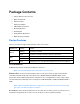
Package Contents • Linksys Wireless Access Point • Quick Start Guide • Ethernet Cable • AC Power Adapter • CD with Documentation • Mounting Bracket • Mounting Kit • Ceiling Mount Back Plate • Drilling Layout Template Device Features There is one indicator light on the front/top of the access point. Light Color Green Blue Red Activity Status Blinking System is starting. Solid System is normal; no wireless devices connected. Blinking Software upgrade in process.
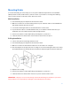
Mounting Guide To avoid overheating, do not install your access point if ambient temperatures exceed 104°F (40°C). Install on a flat, stable surface, near the center of your wireless coverage area making sure not to block vents on the sides of the device enclosure. Wall Installation 1. Position drilling layout template at the desired location. 2. Drill four screw holes on the mounting surface. If your ethernet cable is routed behind the wall, mark ethernet cable hole as well. 3.
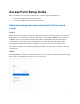
Access Point Setup Guide Once your Linksys access point is installed, choose which way you will manage it: • Remotely, using the Linksys cloud server, or • Locally, through a browser-based user interface Setup to manage your access point with Linksys cloud server Step 1 Make sure the access point is powered on and connected with an ethernet cable to your network with internet access. By factory default, the IP address is assigned by a DHCP server.
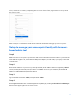
If not, create an account by completing the on-screen forms. Then, register the access point at the new account. We'll send you a confirmation email. Click on the link and finish setting up your access point. Setup to manage your access point locally with browserbased admin tool Step1 Make sure the access point is powered on and connected with an ethernet cable to your network. If the indicator light is off, check that the AC power adapter, or PoE cable, is properly connected on both ends.
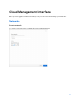
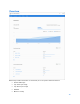
Cloud Management Interface Once you are logged in to Business.Linksys.com you can create and manage your networks.
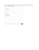
Choose a name for your network and add any descriptive notes about the network. Choose an icon to represent your network.
Overview Overview provides information on a network, its access points and client devices: • Clients and usage • Top clients per usage • Top devices per usage • Channel • Devices on map 10
Access Points Go to Networks and click on a network name. Click on Access Points in the menu bar to manage access points on your network. To add a new access point to the network, click Add access point. 1. Connect your access point to internet. 2. Enter the MAC address and serial number of the access point you want to add, then click Next.
Once the access point has been found, you can rename it and click the Add device button. Monitor Load—Shows the access point’s consumption of CPU load. Memory—Shows the access point’s consumption of memory. Status—Shows the access point’s status for the last seven days Clients and usage—Shows data about clients and traffic for the last seven days. Connected clients—Shows the list of connected clients.
Details View whether the access point is connected to the cloud. See the current firmware version and check for updates. You can also see the MAC address, model number, the name you gave it and any device notes or description. Wireless slot To add a new wireless name to the device, click Add wireless name and select one from the list. Authentication—Shows whether the wireless name is open or requires a password. Broadcast—Shows how many access points in the network are broadcasting the wireless name.
TCP/IP Configure IP—Select Automatic Configuration or Static IP Address. Server IP—Enter an unused IP address from the address range used on your LAN. Gateway—Enter the gateway for IP Server. Subnet mask—Enter the subnet mask for the IP address. Primary DNS server—Enter the DNS Address. Secondary DNS server—Optional. VLAN Tagging—Enter tag of your VLAN.
Tools Ping tool—Determine the accessibility of a host on the network. Blink LED—Make your device LED blink so you can identify it. Rogue access point detection—Detect an unexpected or unauthorized access point installed in a secure network environment.
Time zone—View and edit the device time zone. Local access—The username and password for local access to device. Default is “admin”. Remote syslog status --Decide whether to send logs to a Syslog server and enter the server’s IP address. LED Light—Device LED status. Wireless Create, view and edit names for the wireless names on your networks. To create a new wireless name, choose a network, click Wireless and then + New wireless name .
General Wireless Name—Choose a name and decide whether to broadcast or hide that name. Authentication—Choose whether to protect the wireless name with a password or allow all devices to connect. If using a password, choose a security type - either WEP or WPA2. Status—Enable or disable the wireless name. Disabled wireless names will not be broadcast. Delete wireless name—Remove the wireless name and all settings from the cloud. Be sure to click the Save button when you are finished making changes.
Splash page Enabled/Disabled—Choose whether to send users to a splash page when connecting to the wireless name. Content • • Content o Welcome title—Create a greeting. o Login Instruction—Tell users how to log in. Authentication o Password label—Label the password field. o Success text—Create a message for users who log in successfully. o Failure text—Create a message for users who are unsuccessful logging in.
• Term of use policy o Policy label—Create message to instruct users to confirm they have read your terms of use. o Policy—Create terms of use. Be sure to click the Save button when you are finished making changes. Styles • Style o Logo—Upload a file as a logo for your wireless name. o Colors—Choose colors for background, text and buttons. Be sure to click the Save button when you are finished making changes.
VLAN VLAN tagging—Turn on to enable tags on traffic related to this wireless name. VLAN ID—Choose a VLAN ID. Advanced Client isolation—When turned on, prevents wireless clients from connecting to each other. Maximum concurrent clients—When turned on, limits the number of clients that can be connected at the same time.
Clients Click the settings icon in the far column to view information about a specific client. You also can change the client’s name.
Details MAC address—Client MAC address Name—Custom client label Notes—Client note or description First seen—The first time the client connected Last seen—Last seen client date Connection Duration—How long the client has been connected Traffic—The speed of the connection Signal—The strength of the connection Last seen—The last time the client was connected Wireless Name—The Wi-Fi SSID the client connected to Device IP address—The client’s IP address 22
Settings Select a network and click on the Settings tab. Choose a setting to view or edit. General View or edit a network’s icon, name and any notes. You can also delete a network from cloud management. Access point configuration View or edit a network’s time zone, local login information, remote syslog status and turn the access point’s light on or off. Notifications Decide whether to send email notifications to network members when an access point goes offline.
Account settings To view or edit your account settings, click on your account name and choose Account settings from the drop-down menu. Account Time zone—Set the time zone for your account. Language—Set the language for the user interface.
Profile The profile screen shows your personal data: • Name • Last name • Email • Phone number • Time zone • Language Security Change your account password and view information about users logged in to the cloud management account.
Members Lists all the members of the account. To add a new member to an account, click on New account member. You can also add a new member to your network by clicking the person icon on the far right of the menu bar. Click Invite Member and enter and email address and assign permissions (Manager or Viewer). To transfer ownership of your account, click Transfer ownership and enter the email address of the member you would like to give ownership.
Inventory Inventory is the virtual deposit for the devices you're not using. To add a device, click the Add new access point button. Connect your device to the internet Enter the MAC address and serial number of the device you want to add. Click the Next button. Once the device has been found, rename it and click the Add access point button.
Local Management Interface Setup Wizard (Local Administration) If you are setting up the access point as a standalone device, run the Setup Wizard. If the access point will be part of a cluster – master or slave - go to Configuration > Cluster > Settings & Status page instead. 1. Click the Quick Start tab on the main menu. 2. On the first screen, click Launch... 3. Set the password on the Device Password screen, if desired.
4. Configure the time zone, date and time for the device on System Settings screen. 5. On the IPv4 Address screen configure the IP address of the device (Static or Automatic) then click Next.
6. Set the SSID information on the Wireless Network screen. Click Next. If you want to configure more than four SSIDs, go to Configuration > Wireless > Basic Settings. The access point supports up to eight SSIDs per radio. 7. On the Wireless Security screen, configure the wireless security settings for the device. Click Next. If you are looking for security options that are not available in the wizard, go to Configuration > Wireless Security page.
8. On the Summary screen, check the data to make sure they are correct and then click Submit to save the changes. 9. Click Finish to leave the wizard.
Administration User Accounts Go to Configuration > Administration and select User Accounts to manage user accounts. The access point supports up to five users: one administrator and four normal users. User Account Table User Name Enter the User Name to connect to the access point’s admin interface. User Name is effective once you save settings. User Name can include up to 63 characters. Special characters are allowed.
New Password Enter the Password to connect to the access point’s admin interface. Password must be between 4 and 63 characters. Special characters are allowed. Confirm New Password Re-enter password. Time Go to Configuration > Administration and select Time to configure system time of the device. Time Current Time Display current date and time of the system. Manually Set date and time manually.
Time Zone Choose the time zone for your location from the drop-down list. If your location observes daylight saving time, enable “Automatically adjust clock for daylight saving changes.” Start Time Specify the start time of daylight saving. End Time Specify the end time of daylight saving. Offset Select the adjusted time of daylight saving. NTP NTP Server 1 Enter the primary NTP server. It can be an IPv4 address or a domain name. Valid characters include alphanumeric characters, "_", "-" and ".".
Log Settings Go to Configuration > Administration and select Log Settings to configure logs. Logs record various types of activity on the access point. This data is useful for troubleshooting, but enabling all logs will generate a large amount of data and adversely affect performance. Log Types Log Types Select events to log. Checking all options increase the size of the log, so enable only events you believe are required. Email Alert Email Alert Enable email alert function.
Username Enter the Username to login to your SMTP server. The Username can include up to 32 characters. Special characters are allowed. Password Enter the Password to login to your SMTP server. The Password can include up to 32 characters. Special characters are allowed. Email Address for Logs Enter the email address the log messages are to be sent to. Valid characters include alphanumeric characters, "_", "-", "." and "@". Maximum length is 64 characters.
Management Access Go to Configuration > Administration and select Management Access page to configure the management methods of the access point.
Web Access HTTP HTTP (Hyper Text Transfer Protocol) is the standard for transferring files (text, graphic images and other multimedia files) on the World Wide Web. Enable to allow Web access by HTTP protocol. HTTP Port Specify the port for HTTP. It can be 80 (default) or from 1024 to 65535. HTTP to HTTPS Enable to redirect Web access of HTTP to HTTPS Redirect automatically. This field is available only when HTTP access is disabled.
SNMP v1/v2 Settings Get Community Enter the name of Get Community. Get Community is used to read data from the access point and not for writing data into the access point. Get Community includes 1 to 32 characters. Special characters are allowed. Set Community Enter the name of Set Community. Set Community is used to write data into the access point. The Set Community includes 1 to 32 characters. Special characters are allowed.
SSL Certificate Go to Configuration > Administration and select SSL Certificate to manage the SSL certificate used by HTTPS. Export/Restore to/from Local PC Export SSL Click to export the SSL certificate. Certificate Install Certificate Browse to choose the certificate file. Click Install Certificate. Export to TFTP Server Destination File Enter the name of the destination file. TFTP Server Enter the IP address for the TFTP server.
Restore from TFTP Server Source File Enter the name of the source file. TFTP Server Enter the IP address for the TFTP server. Only support IPv4 Install Click to install the file to the device. address here. LED Lighting Go to Configuration > Administration and select LED Lighting to turn off/on the LED on the front/top of the access point.
LAN Network Setup Go to Configuration > LAN > Network Setup to configure basic device settings, VLAN settings and settings for the LAN interface, including static or dynamic IPv4/IPv6 address assignment. TCP/IP Host Name Assign a host name to this access point. Host name consists of 1 to 15 characters. Valid characters include A-Z, a-z, 0-9 and -. Character cannot be first and last character of hostname and hostname cannot be composed of all digits. VLAN Enables or disables VLAN function.
Untagged Enables or disables VLAN tagging. If enabled (default), traffic from the VLAN LAN port is untagged when the following conditions are met: 1) VLAN ID is equal to Untagged VLAN ID and 2) untagged traffic can be accepted by LAN port. If disabled, traffic from the LAN port is always tagged and only tagged traffic can be accepted from LAN port. By default all traffic on the access point uses VLAN 1, the default untagged VLAN.
Advanced Go to Configuration > LAN > Advanced this screen to configure advanced network settings of the access point. Port Settings Auto If enabled, Port Speed and Duplex Mode will become grey and cannot Negotiation be configured. If disabled, Port Speed and Duplex Mode can be Operational Current Auto Negotiation mode of the ethernet port. configured. Auto Negotiation Port Speed Select the speed of the ethernet port. Available only when Auto Negotiation is disabled.
Duplex Mode Select the duplex mode of the ethernet port. Available only when Auto Negotiation is disabled. The option can be Half or Full (default). Operational Displays the current duplex mode of the ethernet port. Duplex Mode Flow Control Enable or disable flow control of the ethernet port. 802.1x Supplicant 802.1x Enable if your network requires this access point to use 802.1X Supplicant authentication in order to operate.
IGMP/MLD Snooping IGMP IGMP (Internet Group Management Protocol) is a communications Snooping protocol used by hosts and adjacent routers on IP networks to establish multicast group memberships. IGMP is an integral part of IP multicast. IGMP snooping streamlines multicast traffic handling by examining (snooping) IGMP membership report messages from interested hosts, multicast traffic is limited to the subset of ports on which the hosts reside.
Wireless Basic Settings Go to Configuration > Wireless > Basic Settings to configure your wireless radio and SSIDs. Advanced wireless settings such as Band Steering, Channel Bandwidth, are on the Advanced Settings screen. Basic Wireless Settings Wireless Select the wireless radio from the list. Radio Radio 1 is for 2.4 GHz, and Radio 2 is for 5 GHz. Enable Radio Enable or disable the wireless radio.
Wireless Select the desired option for radio 1: Mode G only - allow connection by 802.11G wireless stations only. N only - allow connection by 802.11N wireless stations only. B/G-Mixed - allow connection by 802.11B and G wireless stations only. B/G/N-Mixed (Default) - allow connections by 802.11N, 802.11B and 802.11G wireless stations. Select the desired option for radio 2: N/A-Mixed - allow connection by 802.11A and N wireless stations only. N only - allow connection by 802.11N wireless stations only.
VLAN ID Enter the VLAN ID of the SSID. Used to tag packets which are received from the wireless clients of the SSID and sent from Ethernet or WDS interfaces. Applicable only when VLAN function is enabled. VLAN function can be configured in Configuration -> LAN -> Network Setup screen. Max Clients Enter the number of clients that can connect to the SSID. The range is from 0 to 32 and 0 means no limit.
• WPA2-Personal - This is a further development of WPA-PSK, and offers even greater security, using the AES (Advanced Encryption Standard) method. • WPA/WPA2-Personal - This method, sometimes called Mixed Mode, allows clients to use either WPA-Personal (with TKIP) or WPA2-Personal (with AES). • WPA2-Enterprise - Requires a RADIUS Server on your LAN to provide the client authentication according to the 802.1x standard. Data transmissions are encrypted using the WPA2 standard.
WEP This is the 802.11b standard. Data is encrypted before transmission, but the encryption system is not very strong. WEP Authentication Select Open System or Shared Key. All wireless stations must use the same method. Default Transmit Key Select a transmit key. WEP Encryption Select an encryption option, and ensure your wireless stations have the same setting: 64-Bit Encryption - Keys are 10 Hex characters. 128-Bit Encryption - Keys are 26 Hex characters.
WPA2-Personal This is a further development of WPA-Personal and offers even greater security. WPA2-Personal WPA Algorithm The encryption method is AES. Wireless stations must also use AES. Pre-shared Key Enter the key value. It is 8 to 63 ASCII characters or 64 HEX characters. Other wireless stations must use the same key. Key Renewal Specify the value of Group Key Renewal. It’s a value from 600 to 36000 and default is 3600. WPA automatically changes secret keys after a certain period of time.
WPA/WPA2-Personal This method, sometimes called Mixed Mode, allows clients to use either WPA-Personal or WPA2Personal. WPA/WPA2-Personal WPA Algorithm The encryption method is TKIP or AES. Pre-shared Key Enter the key value. It is 8 to 63 ASCII characters or 64 HEX characters. Other wireless stations must use the same key. Key Renewal Specify the value of Group Key Renewal. It’s a value from 600 to 36000, and default is 3600. WPA automatically changes secret keys after a certain period of time.
WPA2-Enterprise This version of WPA2-Enterprise requires a RADIUS Server on your LAN to provide the client authentication. Data transmissions are encrypted using the WPA2 AES standard. WPA2-Enterprise Primary Server Enter the IP address of the RADIUS Server on your network. Primary Server Port Enter the port number used for connections to the RADIUS Server. It is a value from 1 to 65534, and default is 1812. Primary Shared Enter the key value to match the RADIUS Server.
Backup Shared Enter the key value to match the Backup RADIUS Secret Server. It consists of 1 to 64 characters. WPA Algorithm The encryption method is AES. Key Renewal Specify the value of Group Key Renewal. It is a value Timeout from 600 to 36000, and default is 3600. WPA automatically changes secret keys after a certain period of time. The group key interval is the period of time in between automatic changes of the group key, which all devices on the network share.
WPA/WPA2-Enterprise WPA/WPA2-Enterprise requires a RADIUS Server on your LAN to provide the client authentication. Data transmissions are encrypted using WPA/WPA2 standard. WPA/WPA2-Enterprise Primary Server Enter the IP address of the RADIUS Server on your network. Primary Server Port Enter the port number used for connections to the RADIUS Server. It is a value from 1 to 65534, and default is 1812. Primary Shared Enter the key value to match the RADIUS Server.
Backup Shared Enter the key value to match the Backup RADIUS Secret Server. It consists of 1 to 64 characters. WPA Algorithm The encryption method is TKIP or AES. Key Renewal Specify the value of Group Key Renewal. It is a value Timeout from 600 to 36000, and default is 3600 second. WPA automatically changes secret keys after a certain period of time. The group key interval is the period of time between automatic changes of the group key, which all devices on the network share.
RADIUS Use RADIUS server for authentication and dynamic WEP key generation for data encryption. Authentication Server Primary Server Enter the IP address of the RADIUS Server on your network. Primary Server Port Enter the port number used for connections to the RADIUS Server. It is a value from 1 to 65534, and default is 1812. Primary Shared Enter the key value to match the RADIUS Server. It Secret consists of 1 to 64 characters.
Rogue AP Detection Go to Configuration > Wireless > Rogue AP Detection to detect an unexpected or unauthorized access point installed in a secure network environment. Radio Wireless Radio Select the desired radio from the list. Radio 1 is for 2.4 GHz, and Radio 2 is for 5 GHz. Rogue AP Enable or disable Rogue AP Detection on the selected radio. Detected Rogue AP List Action Click Trust to move the AP to the Trusted AP List. MAC Address The MAC address of the Rogue AP.
Trusted AP List Action Click Untrust to move the AP to the Rogue AP List. MAC Address The MAC address of the Trusted AP. SSID The SSID of the Trusted AP. Channel The channel of the Trusted AP. Security The security method of the Trusted AP. Signal The signal level of the Trusted AP. New MAC Add one trusted AP by MAC address.
Scheduler Go to Configuration > Wireless > Scheduler to configure a rule with a specific time interval for SSIDs to be operational. Automate enabling or disabling SSIDs based on the profile definition. Support up to 16 profiles and each profile can include four time rules. Scheduler Wireless Enable or disable wireless scheduler on the radio. It is Scheduler disabled by default. If disabled, even if some SSIDs are associated with profiles, they will be always active.
Scheduler Operational Status Status The operational status of the scheduler. Reason The detailed reason for the scheduler operational status. It includes the following situations. • System time is outdated. Scheduler is inactive because system time is outdated. • Administrative Mode is disabled. Scheduler is disabled by administrator. • Active Scheduler is active. Scheduler Profile configuration New Profile Name Enter the name for new profile.
Scheduler Association Go to Configuration > Wireless > Scheduler Association to associate defined scheduler profiles with SSIDs. Radio Wireless Radio Select the desired radio from the list. Radio 1 is for 2.4 GHz, and Radio 2 is for 5 GHz. Scheduler Association SSID The index of SSID. SSID Name The name of the SSID. Profile Name Choose the profile that is associated with the SSID. If the profile associated with the SSID is deleted, then the association will be removed.
Connection Control Go to Configuration > Wireless > Connection Control to define whether listed client stations may authenticate with the access point.
SSID Select the desired SSID from the list. Control Type Select the option from the drop-down list as desired. • Local: Choose either “Allow only following MAC addresses to connect to wireless network” or “Prevent following MAC addresses from connection to wireless network.” You can enter up to 20 MAC addresses of wireless stations or choose the MAC address. • RADIUS Primary/Backup RADIUS Server - Enter the IP address of the RADIUS Server.
Rate Limit Go to Configuration > Wireless > Rate Limit to limit downstream and upstream rate of SSIDs. Radio Wireless Radio Select the desired radio from the list. Radio 1 is for 2.4 GHz, and Radio 2 is for 5 GHz. Rate Limit SSID The index of SSID. SSID Name The name of the SSID. Upstream Enter a maximum upstream rate for the SSID. The range is Rate from 0 to 200 Mbps for Radio 1 and from 0 to 600 Mbps Downstream Enter a maximum downstream rate for the SSID.
QoS Go to Configuration > Wireless > QoS (Quality of Service) to specify priorities for different traffic coming from your wireless client. Lower priority traffic will be slowed down to allow greater throughput or less delay for high priority traffic. QoS Setting Wireless Radio Select the desired radio from the list. Radio 1 is for 2.4 GHz, and Radio 2 is for 5 GHz. QoS Settings SSID The index of SSID. SSID Name The name of the SSID. VLAN ID The VLAN ID of the SSID.
Priority Select the priority level from the list. VLAN must be enabled in order to set priority. The 802.1p will be included in the VLAN header of the packets which are received from the SSID and sent from Ethernet or WDS interface. WMM Enable or disable WMM. WMM (Wi-Fi Multimedia) is a component of the IEEE 802.11e wireless LAN standard for QoS. WMM provides prioritization of wireless data packets from different applications based on four access categories: voice, video, best effort, and background.
WDS Go to Configuration > Wireless > WDS (Wireless Distribution System) to expand a wireless network through multiple access points instead of linking them with a wired backbone. The access point can act as WDS Root or WDS Station: • WDS Root - Receives WDS connections from remote WDS Stations. • WDS Station - Connects to remote WDS Root. Supports up to 4 WDS Stations on each wireless radio.
Spanning Tree (recommended if you configure WDS connections) Spanning Tree When enabled, STP helps prevent switching loops. WDS Settings Radio Select the desired radio from the list. Radio 1 is for 2.4 GHz, and Radio 2 is for 5 GHz. WDS Root Interface Enable or Disable the WDS Root. Status Be sure the following settings on WDS Root device are determined and configured. The WDS Station must use the same settings as Root afterwards. • Radio • IEEE 802.
Allowed VLAN Enter the list of VLANs accepted by the WDS Root. List When VLAN is enabled, WDS Root receives from WDS Stations only packets in the VLAN list. Packets not in the list will be dropped. The VLAN list is only applicable when VLAN is enabled. The VLAN list includes 1 to 16 VLAN IDs separated by "," such as "100,200,300,400,500,600,700,800". Security Setting can be Disabled, WPA-Personal, WPA2-Personal, Settings WPA2-Enterprise or WPA/WPA2-Enterprise.
Remote MAC MAC address of the access point on the other end of the Address WDS link. Optional WDS Station connects to remote WDS Root by matching SSIDs. When there is more than one remote WDS Root with the same SSID, the WDS Station can differentiate them by MAC address. The format is xx:xx:xx:xx:xx:xx. VLAN List Enter the list of VLANs that are accepted by the WDS Station. When VLAN is enabled, the WDS Station forwards to the remote WDS Root only packets in the VLAN list.
Workgroup Bridge Go to Configuration > Wireless > Workgroup Bridge to extend the accessibility of a remote network. In Workgroup Bridge mode, the access point acts as a wireless station (STA) on the wireless LAN. It can bridge traffic between a remote wired network and a wireless LAN. When Workgroup Bridge is enabled, SSID configuration still works to provide wireless services to clients. All access points participating in Workgroup Bridge must have the identical settings for Radio interface, IEEE 802.
Workgroup Bridge Radio Select the desired radio from the list. Radio 1 is for 2.4 GHz, and Radio 2 is for 5 GHz. Workgroup Bridge Status Status Enable or disable Workgroup Bridge function. Before configuring Workgroup Bridge, make sure all devices in Workgroup Bridge have the following identical settings. • Radio • IEEE 802.11 Mode • Channel Bandwidth • Channel Note-It is highly recommended that static channel is configured on both APs.
Security Mode Select the desired mode from the list.
Advanced Settings Go to Configuration > Wireless > Workgroup Bridge to configure advanced parameters of wireless radios. Band Steering Band Steering Enable or disable Band Steering function. Band Steering is a technology that detects whether the wireless client is dual-band capable. If it is, band steering pushes the client to connect to the lesscongested 5 GHz network. It does this by actively blocking the client’s attempts to connect with the 2.4GHz network.
Wireless Radio Select the desired radio from the list. Radio 1 is for 2.4 GHz, and Radio 2 is for 5 GHz. Worldwide Mode Worldwide Mode (802.11d) enables the access point (802.11d) to direct connected wireless devices to radio settings Channel Bandwidth Select the designed channel bandwidth for the specific to where in the world the devices are in use. wireless radio. 20MHz - Select if you are not using any 802.11n wireless devices. 20/40MHz - Select if you are using both 802.11n and non-802.
DTIM Interval Enter the Delivery Traffic Information Map (DTIM) period, an integer from 1 to 255 beacons. The default is 1 beacon. The DTIM message is an element included in some beacon frames. It indicates which client stations, currently sleeping in low-power mode, have data buffered on the access point awaiting pickup. The DTIM period that you specify indicates how often the clients served by this WAP device should check for buffered data still on the access point awaiting pickup.
Fragmentation Enter the fragmentation threshold, an integer from Threshold 256 to 2346. The default is 2346. The fragmentation threshold is a way of limiting the size of packets (frames) transmitted over the network. If a packet exceeds the fragmentation threshold you set, the fragmentation function is activated and the packet is sent as multiple 802.11 frames. If the packet being transmitted is equal to or less than the threshold, fragmentation is not used.
Captive Portal Captive Portal is a method of securing access to the Internet from within a wireless network. Users must enter authentication credentials before their wireless client devices can access the Internet. Global Configuration Go to Configuration > Captive Portal > Global Configuration to change settings and modify captive portal authentication access port number if needed. Captive Portal Enable or Disable Captive Portal function globally. Captive Portal is disabled by default.
HTTP Port Once Additional HTTP Port is enabled, define an additional port for HTTP protocol. The value can be 80 or 1024 to 65535 and is 80 by default. The HTTP Port must be different from the HTTP port in Administration > Management Access page. Additional HTTPS HTTPS portal authentication uses the HTTPS Port management port by default. You can configure an HTTPS Port Once Additional HTTPS Port is enabled, define an additional port for that process. additional port for HTTPS protocol.
Portal Profiles Captive Portal Select a profile to configure. Profile Protocol Select the protocol used to access the Portal Authentication web server. It can be HTTP or HTTPS. Authentication Select an authentication method for clients. Local - The access point uses a local database to authenticated wireless clients. Radius - The access point uses a database on a remote RADIUS server to authenticate wireless clients. The RADIUS server must support EAP-MD5.
Radius Authentication Primary Server Enter the IP address of the RADIUS Server on your network. Primary Server Port Enter the port number used for connections to the RADIUS Server. Primary Shared Enter the key value to match the RADIUS Server. Secret Backup Server The Backup Authentication Server will be used when the Primary Authentication Server is not available. Backup Server Port Enter the port number used for connections to the Backup RADIUS Server.
User Name Enter the name of the user account. The user name includes 1 to 32 characters. Special characters except ':' and ';' are allowed. Password Enter the password of the user account. The password must be between 4 and 32 characters in length. Special characters except ':' and ';' are allowed. Confirm Password Re-enter the password to confirm it. Local Group Go to Configuration > Captive Portal > Local Group to configure group settings.
Group Name Enter the name of the new group. The group name includes 1 to 32 characters. Special characters except ':' and ';' are allowed. Click Add. Group Selection Select one group to delete or configure its user members. Members User members of the selected group. You can select one user and click ">>" button to remove it. Other Users Other users which don't belong to the selected group. You can select one user and click "<<" button to add it into the group.
Profile Select a profile to configure. New Logo Upload Logos display in the web page. Select an image file from your local PC and click Upload. Formats .gif, .png and .jpg are supported. File size cannot exceed 5KB. One profile can support one default and one new logo image. If a second new logo is uploaded, it will replace the first new logo. Logo Selection Select a logo image from the list. Background Color The HTML code for the background color in 6-digit hexadecimal format.
Terms of Use Customize the text to go with Terms of Use. Enter up to 512 characters. The default is "Terms of Use". Success Text Customize the text that shows when the client has been authenticated. The default is "You have logged on successfully! Please keep this window open when using the wireless network." Failure Text Customize the text that shows when authentication fails. Enter up to 128 characters.
SSID A list of available SSIDs. SSID Name The name of the SSID. Profile Name Choose the profile that is associated with the SSID. If the profile associated with the SSID is deleted, then the association will be removed. If None is selected, it means no profile is associated. Client Information Go to Configuration > Captive Portal > Client Information to view the status of wireless clients that are authenticated by Captive Portal. MAC Address MAC address of the client.
Away Timeout An authenticated client that has been disconnected from the access point has a specific amount of time within which it may reconnect without reauthentication. The timer starts when the client disconnects from the SSID. After the time reaches zero, the client is de-authenticated. If the timeout is set to 0, the client is not de-authenticated. Measured in seconds. Session Timeout The remaining time of the authenticated session. The timer starts when the client is authenticated.
Clustered access points share these configurations: • User Accounts • SSID Settings • Rate Limit • Time Settings • Wireless Security • QoS • Log Settings • Rogue AP Detection • Advanced Wireless • Management Access • Wireless Scheduler • Discovery Settings • Wireless Scheduler • IGMP/MLD Snooping • Wireless Network Mode Settings • Settings Association • Captive Portal • Wireless Connection Ethernet Port Settings Control • VLAN Settings These configurations and not shar
Type Disabled—Disable the cluster function. Master—Enable the cluster function and assign the access point to be the master. Note— If system detects there is one Master already existed in the same cluster, the new access point that likes to become master will be assigned to slave automatically. Slave—Enable the cluster function and assign the access point to be the slave. Note—When the cluster function is enabled, WDS and workgroup bridge will be disabled automatically.
Status Disabled—Cluster function is disabled. Active—Cluster function is enabled and master is active. Active (Backup Master)—Cluster function is enabled and backup master is active. Inactive (Cannot reach the master)—Cluster function is enabled but it's inactive because device cannot reach the master. Member Number Number of the members active in the cluster. If an access point joins the cluster but is powered off or cannot reach the master, it is not counted.
Client Sessions Go to Configuration > Cluster > Client Sessions to see the status of wireless clients within the cluster. The session is the period of time in which a user on a client device (station) with a unique MAC address maintains a connection with the wireless network. The session begins when the WLAN client logs on to the network, and the session ends when the WLAN client either logs off intentionally or loses the connection for some other reason.
Tx Total The total bytes which are sent to the client by the access point. Unit is Byte. Rx Rate Current transfer rate of the data which are received from the client by the access point. Unit is Kbps. Tx Rate Current transfer rate of the data which are sent to the client by the access point. Unit is Kbps. Channel Management Go to Configuration > Cluster > Channel Management to manage the channel assignments for access points within a cluster.
Auto Channel Auto Channel Access point scans available Wi-Fi channels and changes the channel if better network performance is possible. Disabled by default. Scan Day Choose the day of the week when Auto Channel scans Wi-Fi channels. You may choose specific days or have the access point scan and select the best channel daily. Scan Time Choose the time of day when Auto Channel performs scan.
System Status Status System Summary Go to System Status > Status > System Summary for status of the access point. System Summary Device SKU The SKU is often used to identify device model number and region. Firmware Version The version of the firmware currently installed. Firmware The checksum of the firmware running in the access Checksum point. Hardware Version The version of the hardware. Local MAC The MAC (physical) address of the wireless access Address point.
Host Name The host name assigned to the access point. System Up Time How long the system has been running since the last restart or reboot. System Time The current date and time. Power Source The power source of the access point. It can be Power over Ethernet (PoE) or Power Adapter. When two power sources are plugged in, Power Adaptor will be displayed. Cloud Status Whether cloud management is enabled or disabled.
VLAN VLAN Enabled or disabled (default). Untagged VLAN Enabled (default) or disabled. When enabled, and if its VLAN ID is equal to Untagged VLAN ID, all traffic is untagged when sent from LAN ports. Untagged traffic can be accepted by LAN ports. If disabled, traffic is always tagged when sent from LAN port and only tagged traffic can be accepted from LAN port. By default all traffic on the access point uses VLAN 1, the default untagged VLAN.
IPv6 IP Address The IP address of the wireless access point. Default Gateway Enter the gateway for the LAN segment to which the wireless access point is attached (the same value as the PCs on that LAN segment). Primary DNS The primary DNS address provided by the DHCP server Secondary DNS The secondary DNS address provided by the DHCP or configured manually. server or configured manually.
Radio Status Mode Current 802.11mode (a/b/g/n/ac) of the radio. Current Channel The channel currently in use. Channel Current channel bandwidth of the radio. Bandwidth When set to 20 MHz, only the 20 MHz channel is in use. When set to 20/40 MHz, Wireless-N connections will use 40 MHz channel, but Wireless-B and Wireless-G will still use 20 MHz channel. SSID Status Interface SSID index. SSID Name Name of the SSID. Status Status of the SSID: Enabled or Disabled.
WDS Root Status Status of the WDS Root: Enabled or Disabled. Local MAC MAC Address of the WDS Root. Local SSID Name of the WDS Root. VLAN List VLAN List of the WDS Root. When VLAN function is enabled, WDS Root only receives packets in the VLAN list from WDS Stations and packets not in the list will be dropped. WDS Station Interface The index of WDS Station. Status Status of the WDS Station: Enabled or Disabled. Local MAC MAC Address of the WDS Root.
Wireless Clients Go to System Status > Status > Wireless Clients to see connected clients based on each wireless interface. Wireless Select the desired interface from the list. The interfaces Interface include eight SSIDs per radio. SSID Name Name of the SSID to which the client connects. Client MAC The MAC address of the client. SSID MAC MAC of the SSID to which the client connects. Link Rate The link rate of the client. Unit is Mbps. RSSI The signal strength of the client. Unit is dBm.
Interface Statistics Go to System Status > Status > Statistics to see real-time statistics on data transmitted and received based on each SSID per Radio, and LAN interface. Interface The name of the interface. Wireless Radio Select the desired radio from the list. Radio 1 is for 2.4 GHz, and Radio 2 is for 5 GHz.
Transmit/Receive • Total Packets—The total packets sent (in Transmit table) or received (in Received table) by the interface. • Total Bytes—The total bytes sent (in Transmit table) or received (in Received table) by the interface. • Total Dropped Packets—The total number of dropped packets sent (in Transmit table) or received (in Received table) by the interface. • Total Dropped Bytes—The total number of dropped bytes sent (in Transmit table) or received (in Received table) by the interface.
Log Messages Log Messages Show the log messages. Buttons Refresh Update the data on screen. Save Save the log to a file on your PC. Clear Delete the existing logs from device.
Maintenance Maintenance Firmware Upgrade Go to Maintenance > Maintenance > Firmware Upgrade to upgrade the firmware in the wireless access point by using HTTP/HTTPS, or TFTP. Check the Linksys support website (http://www.linksys.com/support) and download the latest firmware release to a storage device or PC. Perform the firmware upgrade by following the steps below. If an access point works as master of an AP cluster, all slaves within the same cluster will be updated, as well.
To perform the firmware upgrade from TFTP server: 1. Enter the IP address of the TFTP server and the source file. The source file is the firmware filename you stored in your TFTP server. Only IPv4 addresses are supported. 2. Click Upgrade. To perform a firmware upgrade from the Internet: 1. Click Check for Upgrade to see if there is new firmware available. 2. Click the OK on the popup dialogue box to start the firmware download and upgrade if a new version of firmware is available.
Backup/Restore to/from Local PC Backup Once you have the access point working properly, you Configuration should back up the settings to a file on your computer. You can later restore the access point's settings from this file, if necessary. To create a backup file of the current settings: • Click Backup. • If you don't have your browser set up to save downloaded files automatically, locate where you want to save the file, rename it if you like, and click Save.
Factory Default It’s highly recommended you save your current configuration file before you restore to factory default settings. To save your current configuration file, click Maintenance > Configuration Backup/Restore. Factory Default To restore your access point to its factory defaults, select an option and click Save. • Reset All Parameters to Factory Default • No Don’t restore to factory defaults. Reboot Go to Maintenance > Maintenance > Reboot to power cycle the device.
Diagnostics Ping Test Go to Maintenance > Diagnostics > Ping Test to determine the accessibility of a host on the network. General IP Type Enter the IP type of destination address. IP or Domain Enter the IP address or domain name that you want to Name ping. Packet Size Enter the size of the packet. Times to Ping Select the desired number from the drop-list. Ping Result • 5 • 10 • 15 • Unlimited Ping measures how fast you get a response after you've sent out a request.
Packet Capture Go to Maintenance > Diagnostics > Packet Capture to capture and store 802.3 packets received and transmitted by the access point based on one specified network interface. The network interface can be radio, SSID or LAN. Network Interface Select the desired network interface from the dropdown list. The interface can be Radio, SSID or Ethernet. Start Capture Click to start the capture. You will be asked to specify a local file to store the packets. Stop Capture Click to stop the capture.
Appendix A - Troubleshooting Overview This chapter covers some common problems encountered while using the wireless access point, and some possible solutions to them. If you follow the suggested steps and the wireless access point still does not function properly, contact your dealer for further advice. General Problems I can't find new access point on my network. Check the following: • The wireless access point is properly installed, LAN connections are OK, and it is powered ON.
If there is no DHCP Server found, the wireless access point will roll back to an IP address and mask of 192.168.1.252 and 255.255.255.0. My PC can't connect to the LAN via the wireless access point. Check the following: • The SSID and security settings on the PC match the settings on the access point. • On the PC, the wireless mode is set to Infrastructure. • If using the Access Control feature, the PC's name and address is in the Trusted Stations list. • If using 802.1x mode, ensure the PC's 802.
Appendix B - About Wireless LANs Overview Wireless networks have their own terms and jargon. You must understand many of these terms in order to configure and operate a wireless LAN. Wireless LAN Terminology Modes Wireless LANs can work in either of two (2) modes: • Ad-hoc • Infrastructure Ad-hoc Mode Ad-hoc Mode does not require an access point or a wired (Ethernet) LAN. Wireless stations, e.g., notebook PCs with wireless cards, communicate directly with each other.
ESS/ESSID A group of wireless stations, and multiple access points all using the same ID (ESSID), form an Extended Service Set (ESS). Different access points within an ESS can use different channels. To reduce interference, it is recommended that adjacent access points use different channels. As wireless stations are physically moved through the area covered by an ESS, they will automatically change to the access point that has the least interference or best performance.
WPA-PSK In WPA-PSK, like WEP, data is encrypted before transmission. WPA is more secure than WEP. The PSK (pre-shared key) must be entered on each wireless station. The 256-bit encryption key is derived from the PSK, and changes frequently. WPA2-PSK This is a further development of WPA-PSK, and offers even greater security, using the AES (Advanced Encryption Standard) method of encryption. It should be used if possible.
If this option is used: • The access point must have a client login on the RADIUS server. • Each user must have a user login on the RADIUS server. • Each user's wireless client must support 802.1X and provide the login data when required. • All data transmission is encrypted using the WEP standard. You only have to select the WEP key size; the WEP key is automatically generated.
Appendix C - PC and Server Configuration Overview All wireless stations need to have settings that match the wireless access point. These settings depend on the mode in which the access point is being used. • If using WEP or WPA2-PSK, it is only necessary to ensure that each wireless station's settings match those of the wireless access point, as described below. • For 802.1x modes, configuration is much more complex.
Using WPA2-PSK For each of the following items, each wireless station must have the same settings as the wireless access point. Mode On each PC, the mode must be set to Infrastructure. SSID (ESSID) This must match the value used on the wireless access point. The default value is LinksysSMB24G for radio 1 and LinksysSMB5G for radio 2. Note—The SSID is case sensitive. Wireless Security On each client, wireless security must be set to WPA2-PSK.
RADIUS Server Configuration If using WPA2-Enterprise mode, the RADIUS server on your network must be configured as follows: • It must provide and accept certificates for user authentication. • There must be a client login for the wireless access point itself. • The wireless access point will use its default name as its client login name. (However, your RADIUS server may ignore this and use the IP address instead.
• World Wide Web Server—Select World Wide Web Server on the Internet Information Services (IIS) component. • From the Networking Services category, select Dynamic Host Configuration Protocol (DHCP), and Internet Authentication Service (DNS should already be selected and installed). 4. Click Next. 5. Select Enterprise root CA and click Next.
6. Enter the information for the Certificate Authority and click Next. 7. Click Next if you don't want to change the CA's configuration data. 8. Installation will warn you that Internet Information Services are running, and must be stopped before continuing. Click OK, then Finish. DHCP server configuration 1. Click on Start > Programs > Administrative Tools > DHCP. 2. Right-click on the server entry and select New Scope. 3. Click Next when the New Scope Wizard Begins.
4. Enter the name and description for the scope, click Next. 5. Define the IP address range. Change the subnet mask if necessary. Click Next. 6. Add exclusions in the address fields if required. If no exclusions are required, leave it blank. Click Next. 7. Change the Lease Duration time if preferred. Click Next. 8. Select Yes, I want to configure these options now, and click Next. 9. Enter the router address for the current subnet. The router address may be left blank if there is no router. Click Next. 10.
12. Select Yes, I want to activate this scope now. Click Next, then Finish. 13. Right-click on the server and select Authorize. It may take a few minutes to complete. Certificate Authority Setup 1. Select Start > Programs > Administrative Tools > Certification Authority. 2. Right-click Policy Settings and select New > Certificate to Issue. 3. Select Authenticated Session and Smartcard Logon (select more than one by holding down the Ctrl key). Click OK. 4.
5. Right-click on your active directory domain and select Properties. 6. Select the Group Policy tab, choose Default Domain Policy then click Edit.
7. Select Computer Configuration > Windows Settings > Security Settings > Public Key Policies, right-click Automatic Certificate Request Settings > New > Automatic Certificate Request. 8. When the Certificate Request Wizard appears, click Next. 9. Select Computer, click Next. 10. Ensure that your Certificate Authority is checked, click Next. 11. Review the policy change information and click Finish. 12. Click Start > Run, type “cmd” and press Enter. Enter “secedit /refreshpolicy machine_policy”.
Internet Authentication Service (RADIUS) Setup 1. Select Start > Programs > Administrative Tools > Internet Authentication Service. 2. Right-click on Clients and select New Client. 3. Enter a name for the access point, click Next. 4. Enter the address or name of the wireless access point, and set the shared secret, as entered on the Security Settings of the wireless access point. 5. Click Finish. 6. Right-click on Remote Access Policies, select New Remote Access Policy. 7.
9. Click Permitted, then OK. Select Next. 10. Select Grant remote access permission. Click Next. 11. Click Edit Profile... and select the Authentication tab. Enable Extensible Authentication Protocol and select Smart Card or other Certificate. Deselect other authentication methods listed. Click OK. 12. Select No if you don't want to view the help for EAP. Click Finish.
Remote Access Login for Users 1. Select Start > Programs > Administrative Tools > Active Directory Users and Computers. 2. Double-click on the user who you want to enable. 3. Select the Dial-in tab and enable Allow access. Click OK. 802.1x Client Setup on Windows XP Windows XP ships with a complete 802.1x client implementation. If using Windows 2000, you can install SP3 (Service Pack 3) to gain the same functionality. If you don't have either of these systems, you must use the 802.
Client Certificate Setup 1. Connect to a network that doesn't require port authentication. 2. Start your Web browser. In the address box, enter the IP address of the Windows 2000 Server, followed by “/certsrv”, e.g., “http://192.168.0.2/certsrv”. 3. You will be prompted for a user name and password. Enter the User name and Password assigned to you by your network administrator and click OK. 4. On the first screen (below), select Request a certificate, click Next.
5. Select User certificate request and select User Certificate, click Next. 6. Click Submit.
7. A message will be displayed, and the certificate will be returned to you. Click Install this certificate. 8. You will receive a confirmation message. Click Yes. 9. Certificate setup is now complete.
802.1x Authentication Setup 1. Select Start > Control Panel > Network Connections. 2. Right-click on the Wireless Network Connection and select Properties. 3. Select the Authentication tab and ensure that Enable network access control using IEEE 802.1X is selected, and Smart Card or other Certificate is selected from the EAP type. Encryption Settings The encryption settings must match the access point on the wireless network you wish to join.
Enabling Encryption To enable encryption for a wireless network: 1. Click on the Wireless Networks tab. 2. Select the wireless network from the Available networks list and click Configure.
3. Select and enter the correct values, as advised by your Network Administrator. For example, to use EAP-TLS, you would enable Data encryption, and click the checkbox for the setting The key is provided for me automatically, as shown below. 4. Setup for Windows XP and 802.1x client is now complete. Using 802.1x Mode (without WPA) This is very similar to using WPA-Enterprise. The only difference is that on your client, you must NOT enable the setting The key is provided for me automatically.
Instead, you must enter the WEP key manually, ensuring it matches the WEP key used on the access point. Note—On some systems, the 64-bit WEP key is shown as 40-bit and the 128-bit WEP key is shown as 104-bit. This difference arises because the key input by the user is 24 bits less than the key size used for encryption. Regulatory Approvals Federal Communication Commission Interference Statement This device complies with Part 15 of the FCC Rules.
This equipment has been tested and found to comply with the limits for a Class B digital device, pursuant to Part 15 of the FCC Rules. These limits are designed to provide reasonable protection against harmful interference in a residential installation. This equipment generates, uses and can radiate radio frequency energy and, if not installed and used in accordance with the instructions, may cause harmful interference to radio communications.
Caution (i) the device for operation in the band 5150-5250 MHz is only for indoor use to reduce the potential for harmful interference to co-channel mobile satellite systems; (ii) high-power radars are allocated as primary users (i.e. priority users) of the bands 5250-5350 MHz and 5650-5850 MHz and that these radars could cause interference and/or damage to LELAN devices.