User Guide SMART SWITCH LGS3XX 1
Contents Chapter 1 – Getting Started ............................................................................... 5 Chapter 2 – System Status ................................................................................. 9 System Summary .................................................................................................................................... 9 RMON.................................................................................................................................
MSTP Properties................................................................................................................................... 98 MSTP Instance Status ..................................................................................................................... 101 MSTP Instance Interface ................................................................................................................ 102 Chapter 8 - MAC Address Management ..........................................
Chapter 13 - Access Control List ............................................................... 168 MAC-Based ACL ................................................................................................................................ 169 MAC-Based ACE ................................................................................................................................ 170 IPv4-Based ACL ......................................................................................................
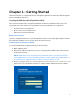
Chapter 1 – Getting Started There are two ways to configure the device: through the graphical user interface and through the menu command line interface. Starting the Web-based Configuration Utility This section describes how to navigate the Web-based switch configuration utility. If you are using a pop-up blocker, make sure it is disabled.
Logging Out By default, the application logs out after ten minutes of inactivity. CAUTION Unless the Running Configuration is copied to the Startup Configuration, rebooting the device will remove all changes made since the last time the file was saved. Save the Running Configuration to the Startup Configuration before logging off to preserve any changes you made during this session. When you click Quick Start > Save Your Configurations, the Configuration File Copy page appears.
Management Buttons The following table describes the commonly used buttons that appear on various pages in the system. Button Name Description Add Click to display the related Add page and add an entry to a table. Enter the information and click Apply to save it to the Running Configuration. Click Close to return to the main page. Click Save to display the Configuration File Copy page and save the Running Configuration to the Startup Configuration file type on the device.
Configuring with Menu Command Line Interface To configure with the device through the menu CLI: 1. Log on to the device through telnet. 2. Configure the device. 3. Click Logout.
Chapter 2 – System Status System Summary The System Summary page provides a graphic view of the device, and displays device status, hardware information, firmware version information, general PoE status, and other items. To view system information, click System Status > System Summary. The System Summary page contains system and hardware information. • System Mode—Specifies whether the system is operating in Layer 2 system mode. • System Description—A description of the system.
• Firmware Version—Firmware version number. • Boot Code Version—Boot version number. • Hardware Version —Hardware version number of the device. • Serial Number—Serial number. Device Status • Fan Status—Applicable only to models that have fans. The following values are possible: o OK—Fan is operating normally. o Fail—Fan is not operating correctly. • Date & Time—System date and time. • System Uptime—Length of time since last reboot.
• Received (Rx) error event has not been detected. • Packet has a valid CRC. To view RMON statistics and/or set the refresh rate: 1. Click System Status > RMON > Statistics. 2. Select the Interface for which statistics are to be displayed. 3. Select the Refresh Rate, the time period that passes before the interface statistics are refreshed. The statistics are displayed for the selected interface.
• Frames of 256 to 511 Bytes—Number of frames, containing 256-511 bytes that were received. • Frames of 512 to 1023 Bytes—Number of frames, containing 512-1023 bytes that were received. • Packets of 1024 and More Bytes—Number of frames, containing 1024- 2000 bytes, and Jumbo Frames, that were received. To clear or view statistics counters: • Click Refresh to refresh the counters on the page. • Click Clear to clear the selected interfaces counters.
• Sampling Interval—Enter the time in seconds that samples are collected from the ports. The field range is 1-3600. • Owner—Enter the RMON station or user that requested the RMON information. 4. Click Apply. The entry is added to the History Control Table page, and the Running Configuration file is updated. 5. Click the History button (described below) to view the actual statistics. RMON History Table The History Table page displays interface-specific statistical network samplings.
• Fragments—Fragments (packets with less than 64 octets) received, excluding framing bits, but including FCS octets. • Jabbers—Total number of received packets that were longer than 2000 octets. This number excludes frame bits, but includes FCS octets that had either a bad FCS (Frame Check Sequence) with an integral number of octets (FCS Error) or a bad FCS with a non-integral octet (Alignment Error) number. • Collisions—Collisions received.
o Log (Event Log Table)—Add a log entry to the Event Log table when the alarm is triggered. o Trap (SNMP Manager and SYSLOG Server)—Send a trap to the remote log server when the alarm goes off. o Log and Trap—Add a log entry to the Event Log table and send a trap to the remote log server when the alarm goes off. • Last Event Time—Displays the time of the event. (This is a read-only table in the parent window and cannot be defined). • Owner—Enter the device or user that defined the event. 4.
RMON Alarms RMON alarms provide a mechanism for setting thresholds and sampling intervals to generate exception events on counters or any other SNMP object counter maintained by the agent. Both the rising and falling thresholds must be configured in the alarm. After a rising threshold is crossed, no rising events are generated until the companion falling threshold is crossed. After a falling alarm is issued, the next alarm is issued when a rising threshold is crossed.
• Falling Threshold—Enter the value that triggers the falling threshold alarm. • Startup Alarm—Select the first event from which to start generation of alarms. Rising is defined by crossing the threshold from a low-value threshold to a highervalue threshold. o Rising Alarm—A rising value triggers the rising threshold alarm. o Falling Alarm—A falling value triggers the falling threshold alarm. o Rising and Falling—Both rising and falling values trigger the alarm.
To display Ethernet statistics and/or set the refresh rate: 1. Click System Status > Interface Statistics. 2. Enter the parameters. o Interface—Select the specific interface for which Ethernet statistics are to be displayed. o Refresh Rate—Select the time period that passes before the interface Ethernet statistics are refreshed. The available options are as follows: - No Refresh—Statistics are not refreshed. - 15 Sec—Statistics are refreshed every 15 seconds.
Chapter 3 – Quick Start To simplify device configuration through quick navigation, the Quick Start page provides links to the most commonly used pages. Link Name (on the Page) Linked Page Configure User Accounts and User Access & Accounts Management Access Configure Device IP Address IPv4 Interface Create VLANs VLANs Configure VLAN Memberships VLAN Memberships Save Your Configuration Configuration File Copy Clicking on the Support link takes you to the device product support page.
Chapter 4 – System Management System Information To enter system information: 1. Click Configuration > System Management > System Information. 2. View or modify the system settings. • System Description—Displays a description of the device. • System Location—Enter the location where the device is physically located. • System Contact—Enter the name of a contact person. • System Host Name—Select the host name of this device.
Management Session Timeout The Management Session Timeout configures the time intervals that the management sessions can remain idle before they timeout and you must log in again to reestablish the session. To set the idle session timeout for various types of sessions: 1. Click Configuration > System Management > Management Session Timeout. 2. Select the timeout for the following sessions from the corresponding list. The default timeout value is 10 minutes.
Clock Source System time can be set manually by the user, or dynamically from an SNTP server. If an SNTP server is chosen, the manual time settings are overwritten when communications with the server are established. As part of the boot process, the device always configures the time, time zone, and DST. These parameters are obtained from SNTP, values set manually, or if all else fails, from the factory defaults. • Manual—User must manually set the time. • SNTP—Time can be received from SNTP time servers.
• If the server supplying the source parameters fails, or dynamic configuration is disabled by the user, the manual settings are used. • Dynamic configuration of the time zone and DST continues after the IP address lease time has expired. • Manual configuration of the time zone and DST becomes the Operational time zone and DST, only if the dynamic configuration is disabled or fails. Note—The DHCP server must supply DHCP option 100 in order for dynamic time zone configuration to take place.
2. Enter these parameters: Clock Source • SNTP-If you enable this, the system time is obtained from an SNTP server. To use this feature, you must also configure a connection to an SNTP server in the SNTP Unicast Server page. • SNTP Client Unicast-Select to enable client Unicast mode. • SNTP IPv4 Multicast Rx-Select to receive SNTP IPv4 Multicast synchronization packets requesting system time information. The packets are transmitted to all SNTP servers on the subnet.
• Daylight Saving Type o USA - DST is set according to the dates used in the USA. o European - DST is set according to the dates used by the European Union and other countries that use this standard. o By Dates - DST is set manually, typically for a country other than the USA or a European country. This allows customization of the start and stop of DST. - From - Date and time that DST starts. - To - Date and time that DST ends. o Recurring From / Recurring To) - DST occurs on the same date every year.
To add a Unicast SNTP server: 1. Click Configuration > System Management > Time > SNTP Unicast Server. This page displays the following information for each Unicast SNTP server: • SNTP Server—SNTP server IP address. The preferred server, or hostname, is chosen according to its stratum level. • SNTP Server Status—SNTP server status. The possible values are: - Up—SNTP server is currently operating normally. - Down—SNTP server is currently not available.
• Link Local—The IPv6 address uniquely identifies hosts on a single network link. A link local address has a prefix of FE80, is not routable, and can be used for communication only on the local network. Only one link local address is supported. If a link local address exists on the interface, this entry replaces the address in the configuration. • Link Local Interface—Select the link local interface (if IPv6 AddressType Link Local is selected) from the list.
Note—Due to the security vulnerabilities of other versions, it is recommended to use SNMPv3. • SNMPv3 In addition to the functionality provided by SNMPv1 and v2, SNMPv3 applies access control and new trap mechanisms to SNMPv1 and SNMPv2 PDUs. SNMPv3 also defines a User Security Model (USM) that includes: o Authentication—Provides data integrity and data origin authentication. o Privacy—Protects against disclosure message content. Cipher Block- Chaining (CBC-DES) is used for encryption.
2. Optionally, define SNMP view(s) by using the Views page. This limits the range of Object IDs available to a community or group. 3. Define groups by using the Groups page. 4. Define users by using the SNMP Users page, where they can be associated with a group. If the SNMP Engine ID is not set, then users may not be created. 5. Optionally, enable or disable traps by using the Trap Settings page. 6. Optionally, define a notification filter(s) by using the Notification Filter page. 7.
Feature Configuration The Engine ID is used by SNMPv3 entities to uniquely identify them. An SNMP agent is considered an authoritative SNMP engine. This means that the agent responds to incoming messages (Get, GetNext, GetBulk, Set) and sends trap messages to a manager. The agent's local information is encapsulated in fields in the message. Each SNMP agent maintains local information that is used in SNMPv3 message exchanges.
o Use Default—Select to use the device-generated engine ID. The default engine ID is based on the device MAC address, and is defined per standard as: - First 4 octets—First bit = 1, the rest is the IANA enterprise number. - Fifth octet—Set to 3 to indicate the MAC address that follows. - Last 6 octets—MAC address of the device. - None—No engine ID is used. o User Defined—Enter the local device engine ID. The field value is a hexadecimal string (range: 10 - 64).
Views A view is a user-defined label for a collection of MIB subtrees. Each subtree ID is defined by the Object ID (OID) of the root of the relevant subtrees. Either well- known names can be used to specify the root of the desired subtree or an OID can be entered (see Device Model Object IDs). Each subtree is either included or excluded in the view being defined. The Views page enables creating and editing SNMP views. The default views (Default, DefaultSuper) cannot be changed.
4. Include or exclude the MIB object from the view. If Include Object is selected, the MIB objects are included in the view, otherwise they are excluded. 5. Click Apply. 6. In order to verify your view configuration, select the user-defined views from the View Name list. The following views exist by default: • Default—Default SNMP view for read and read/write views. • DefaultSuper—Default SNMP view for administrator views. Other views can be added.
SNMPv3 provides a means of controlling the content each user can read or write and the notifications they receive. A group defines read/write privileges and a level of security. It becomes operational when it is associated with an SNMP user or community. Note—To associate a non-default view with a group, first create the view in the Views page. To create an SNMP group: 1. Click Configuration > System Management>SNMP > Groups. This page displays the existing SNMP groups and their security levels.
o Security Level—Define the security level attached to the group. SNMPv1 and SNMPv2 support neither authentication nor privacy. If SNMPv3 is selected, select to enable one of the following: o No Authentication and No Privacy—Neither the Authentication nor the Privacy security levels are assigned to the group. o Authorized View—Select the Read, Write and Notify views associated with this group and with the above security level.
Groups enable network managers to assign access rights to a group of users instead of to a single user. A user can only belong to a single group. To create an SNMPv3 user, the following must first exist: An engine ID must first be configured on the device. This is done in the Engine ID page. An SNMPv3 group must be available. An SNMPv3 group is defined in the Groups page. To display SNMP users and define new ones: 1. Click Configuration > System Management>SNMP > Users. This page contains existing users. 2.
• Authentication Password—If authentication is accomplished by either a MD5 or a SHA password, enter the local user password in either Encrypted or Plaintext. Local user passwords are compared to the local database, and can contain up to 32 ASCII characters. • Privacy Method—Select one of the following options: o None—Privacy password is not encrypted. o DES—Privacy password is encrypted according to the Data Encryption Standard (DES).
• Advanced Mode—The access rights of a community are defined by a group (defined in the Groups page). You can configure the group with a specific security model. The access rights of a group are Read, Write, and Notify. To define SNMP communities: 1. Click Configuration > System Management>SNMP > Communities. This page contains a table of configured SNMP communities and their properties. 2. Click Add. This page enables network managers to define and configure new SNMP communities. 3.
o Read Write—Management access is read-write. Changes can be made to the device configuration, but not to the community. o SNMP Admin—User has access to all device configuration options, as well as permissions to modify the community. SNMP Admin is equivalent to Read Write for all MIBs except for the SNMP MIBs. SNMP Admin is required for access to the SNMP MIBs. o View Name—Select an SNMP view (a collection of MIB subtrees to which access is granted).
3. Enter the parameters. • Filter Name—Enter a name between 0-30 characters. • Filter Object—Select the node in the MIB tree that is included or excluded in the selected SNMP filter. The options to select the object are as follows: o Selection List—Enables you to navigate the MIB tree. Press the Up arrow to go to the level of the selected node's parent and siblings; press the Down arrow to descend to the level of the selected node's children. Click nodes in the view to pass from one node to its sibling.
The Notification Recipients SNMPv1/v2 page and the Notification Recipients SNMPv3 page enable configuring the destination to which SNMP notifications are sent, and the types of SNMP notifications that are sent to each destination (traps or informs). The Add/Edit pop-ups enable configuring the attributes of the notifications. An SNMP notification is a message sent from the device to the SNMP management station indicating that a certain event has occurred, such as a link up/ down.
• Filter Name—Select the SNMP filter that defines the information contained in traps (defined in the Notification Filter page). 3. Click Apply. The SNMP Notification Recipient settings are written to the Running Configuration file. V3 Notification Recipients To define a recipient in SNMPv3: 1. Click SNMP > Notification Recipients SNMPv3. This page displays recipients for SNMPv3. 2. Enter the fields: • IP Version—Select either IPv4 or IPv6.
• Notification Version—Select SNMP v3. • Notification Type—Select whether to send traps or informs. If both are required, two recipients must be created. • Timeout—Enter the amount of time (seconds) the device waits before re- sending informs/traps. Timeout: Range 1-300, default 15. • Retries—Enter the number of times that the device resends an inform request. Retries: Range 1-255, default 3. • User Name—Select from the drop-down list the user to whom SNMP notifications are sent.
In addition, you can send messages to remote SYSLOG servers in the form of SNMP traps and SYSLOG messages. You can configure the messages that are written to each log by severity, and a message can go to more. Log Management You can select the events by severity level. Each log message has a severity level marked with the first letter of the severity level separated by dashes (-) on each side (except for Emergency that is indicated by the letter F).
For example, if Warning is selected, all severity levels that are Warning and higher are stored in the log (Emergency, Alert, Critical, Error, and Warning). No events with severity level below Warning are stored (Notice, Informational, and Debug). To set global log parameters: 1. Click Configuration > System Management > Logs > Log Management. 2. Enter the parameters: • System Log o Logging—Select to enable message logging. o Originator Identifier—Enables adding an origin identifier to SYSLOG messages.
Remote Log Servers The Remote Log Servers page enables defining remote SYSLOG servers where log messages are sent (using the SYSLOG protocol). For each server, you can configure the severity of the messages that it receives. To define SYSLOG servers, do the following: 1. Click Configuration > System Management > Logs > Remote Log Servers. 2. Click Add. 3. Enter the parameters. • Enter New Server o Remote Log Server—Select whether to identify the remote log server by IP address or name.
o Log Server IP Address—Enter the IP address of the log server if it is to be identified by address. o Log Server Name—Enter the domain name of the log server if it is to be identified by name. • Server Settings o UDP Port—Enter the UDP port to which the log messages are sent. o Facility—Select a facility value from which system logs are sent to the remote server. Only one facility value can be assigned to a server. If a second facility code is assigned, the first facility value is overridden.
• Severity—Event severity. • Description—Message text describing the event. To clear the log messages, click Clear. Flash Memory Log The Flash Memory Log page displays the messages that were stored in the Flash memory, in chronological order. The minimum severity for logging is configured in the Log Management page. Flash logs remain when the device is rebooted. You can clear the logs manually. Click Configuration > System Management > Logs > Flash Memory Log. • Log Index—Log entry number.
Chapter 5 – Port Management Ports To configure port settings: 1. Click Configuration > Port Management > Ports. 2. Select Enable to support jumbo packets of up to 10 KB in size. If Jumbo Frames is not enabled (default), the system supports packet size up to 2,000 bytes. For Jumbo Frames to take effect, the device must be rebooted after the feature is enabled. 3. To update the port settings, select the desired port, and click Edit.
o Protected Port—Select to make this a protected port. (A protected port is also referred to as a Private VLAN Edge.) Features of a protected port: - Protected Ports provide Layer 2 isolation between interfaces (Ethernet ports and LAGs) that share the same VLAN. - Packets received from protected ports can be forwarded only to unprotected egress ports. Protected port filtering rules are also applied to packets that are forwarded by software, such as snooping applications.
o Back Pressure—Used with Half Duplex mode to slow down the packet reception speed when the device is congested. It disables the remote port, preventing it from sending packets by jamming the signal. o Flow Control—Enable or disable 802.3x Flow Control, or enable the Auto Negotiation of flow control on the port (only when in Full Duplex mode). o MDI/MDIX—Media Dependent Interface/Media Dependent o Interface with Crossover status on the port.
This switch supports two modes of load balancing. • By MAC Addresses—(Default) Based on the destination and source MAC addresses of all packets. • By IP and MAC Addresses—Based on the destination and source IP addresses for IP packets, and destination and source MAC addresses for non-IP packets. LAG Management In general, a LAG is treated by the system as a single logical port. In particular, the LAG has port attributes similar to a regular port, such as state and speed. The device supports four LAGs.
LAGs The LAGs page enables you to configure the global settings, and to select and edit the desired LAG on the Edit LAG Membership page. To define the member or candidate ports in a LAG: 1. Click Configuration > Port Management > Link Aggregation > LAGs. 2. Select the Load Balance Method • by MAC Address—(Default) Based on the destination and source MAC addresses of all packets.
o Auto Negotiation—Select to enable auto-negotiation on the LAG. Autonegotiation is a protocol between two link partners that enables a LAG to advertise its transmission speed and flow control to its partner (the Flow Control default is disabled). It is recommended to keep auto-negotiation enabled on both sides of an aggregate link, or disabled on both sides, while ensuring that link speeds are identical. o Port Speed—Configure the speed of the LAG. The port types determine the available speeds.
Green Ethernet Green Ethernet is a common name for a set of features that is designed to be environmentally friendly, and to reduce the power consumption of a device. Green Ethernet is different from EEE in that Green Ethernet energy-detect is enabled on all devices where only the gigabyte ports are enabled with EEE. The Green Ethernet feature can reduce overall power usage in the following ways. • Short-Reach Mode—Provides for power savings on a short length of cable.
Power savings, current power consumption and cumulative energy saved can be monitored. The total amount of saved energy can be viewed as a percentage of the power that would have been consumed by the physical interfaces had they not been running in Green Ethernet mode. The saved energy displayed is only related to Green Ethernet. The amount of energy saved by EEE is not displayed. Energy Efficient Ethernet EEE is designed to save power when there is no traffic on the link.
Note—If Auto-Negotiation is not enabled on a port, the EEE is disabled. The only exception is if the link speed is 1GB, then EEE will still be enabled even though Auto-Negotiation is disabled. Default Configuration By default, 802.3 EEE is enabled globally and per port. Interactions Between Features 802.3 EEE interactions with other features: • If auto-negotiation is not enabled on the port, the 802.3 EEE operational status is disabled.
Note—If Short Reach is enabled, EEE must be disabled. • 802.3 Energy Efficient Ethernet (EEE)—Select to globally enable EEE. 2. Click Apply to set the global settings. • Power Savings—The percentage of power saved by running Green Ethernet and Short Reach. The power savings displayed is only relevant to the power saved by Short Reach and Energy Detect modes. The EEE power savings is dynamic by nature since it is based on port utilization and is therefore not taken into consideration.
PoE capabilities: • Eliminates the need to run 110/220 V AC power to all devices on a wired LAN. • Removes the necessity for placing all network devices next to power sources. • Eliminates the need to deploy double cabling systems in an enterprise, significantly decreasing installation costs.
PoE Priority Example A 48-port device is supplying a total of 375 watts. The administrator configures all ports to allocate up to 30 watts each. This results in 48 times 30 ports equaling 1440 watts, which is too much. The device cannot provide enough power to each port, so it provides power according to the priority.The administrator sets the priority for each port, allocating how much power it can be given. These priorities are entered in the PoE Port Limit Mode or Class Limit Power Mode pages.
o To prevent false detection, you should disable PoE on the ports on the PoE switches that are used to connect to PSEs. You should also first power up a PSE device before connecting it to a PoE device. When a device is being falsely detected as a PD, you should disconnect the device from the PoE port and power cycle the device with AC power before reconnecting its PoE ports. Feature Configuration The Feature Configuration page enables selecting either the Port Limit or Class Limit PoE mode.
• Consumed Power—Amount of power in watts that is currently being consumed by the PoE ports. • Available Power—Nominal power in watts minus the amount of consumed power. 3. Click Apply to save the PoE properties. Port Limit Power Mode To configure port limit power mode: 1. Click Configuration > Port Management > PoE > Port Limit Power Mode. The list of fields below is for Port Limit Power Mode. • PoE Status—Enable or disable PoE on the port.
Class Limit Power Mode To configure class limit power mode: 1. Click Configuration > Port Management > PoE > Class Limit Power Mode. • PoE Status—Enable or disable PoE on the port. • Power Priority Level—Port priority is low, high, or critical, for use when the power supply is low. For example, if the power supply is running at 99% usage and port 1 is prioritized as high, but port 3 is prioritized as low, port 1 receives power and port 3 might be denied power. • Class—Class configured on this port.
2. Select a port and click Edit. Enter the fields as described above. 3. Click Apply. The PoE settings for the port are written to the Running Configuration file. Discovery - LLDP Link Layer Discovery Protocol (LLDP) is a link layer protocol for directly-connected LLDP-capable neighbors to advertise themselves and their capabilities. LLDP enables network managers to troubleshoot and enhance network management in multi-vendor environments.
The operation of LLDP is independent of the STP status of an interface. If 802.1x port access control is enabled at an interface, the device transmits and receives LLDP packets to and from the interface only if the interface is authenticated and authorized. If a port is the target of mirroring, then LLDP considers it down. Note—LLDP are link layer protocols for directly-connected LLDP capable devices to advertise themselves and their capabilities.
The LLDP-MED TLVs to be advertised can be selected in the LLDP MED Port Settings page, and the management address TLV of the device may be configured to be advertised. To configure the LLDP port settings: 1. Click Configuration > Port Management > Discovery – LLDP > Feature Configuration. The following fields are displayed (only fields that do not appear in the Edit page are described): • Interface—The port to edit. • LLDP MED Status—Enabled or disabled.
o Port Description—Information about the port, including manufacturer, product name and hardware/software version. o System Name—System's assigned name (in alpha-numeric format). The value equals the sysName object. o System Description—Description of the network entity (in alpha-numeric format). This includes the system's name and versions of the hardware, operating system, and networking software supported by the device. The value equals the sysDescr object.
LLDP MED Ports The LLDP MED Ports page enables the selection of the LLDP MED TLVs and/or the network policies to be included in the outgoing LLDP advertisement for the desired interfaces. Network Policies are configured using the LLDP MED Network Policy page. To configure LLDP MED on each port: 1. Click Configuration > Port Management > Discovery – LLDP > LLDP MED Ports.
• Available Network Policies—Select the LLDP MED policies to be published by LLDP by moving them from the Available Network Policies list. These were created in the LLDP MED Network Policy page. To include one or more user-defined network polices in the advertisement, you must also select Network Policy from the Available Optional TLVs. Note—The following fields must be entered in hexadecimal characters in the exact data format that is defined in the LLDP-MED standard (ANSI-TIA1057_final_for_publication.
To view the LLDP local port status advertised on a port: 1. Click Configuration > Port Management Discovery - LLDP > LLDP Local Information. 2. Select the desired port from the Port list. This page displays the following groups of fields (the actual fields displayed depend on the optional TLVs selected to be advertised): • • • Global o Chassis ID Subtype—Type of chassis ID. (For example, the MAC address.) o Chassis ID—Identifier of chassis.
• • o Endpoint Class 2—Media endpoint class, offering media streaming capabilities, as well as all Class 1 features. o Endpoint Class 3—Communications device class, offering all Class 1 and Class 2 features plus location, 911, Layer 2 device support, and device information management capabilities. o PoE Device Type—Port PoE type; for example, powered. o PoE Power Source—Port power source. o PoE Power Priority—Port power priority. o PoE Power Value—Port power value.
LLDP Neighbor Information The LLDP Neighbors Information page contains information that was received from neighboring devices. After timeout (based on the value received from the neighbor Time To Live TLV during which no LLDP PDU was received from a neighbor), the information is deleted. To view the LLDP neighbor information: Click Configuration>Port Management > Discovery - LLDP > LLDP Neighbor Information.
• • • o Supported System Capabilities—Primary functions of the device. The capabilities are indicated by two octets. Bits 0 through 7 indicate Other, Repeater, Bridge, WLAN AP, Router, Telephone, DOCSIS cable device, and station, respectively. Bits 8 through 15 are reserved. o Enabled System Capabilities—Primary enabled function(s) of the device. Management Address o Address Subtype—Managed address subtype; for example, MAC or IPv4. o Address—Managed address. o Interface Subtype—Port subtype.
o Civic—Civic or street address. o Coordinates—Location map coordinates—latitude, longitude, and altitude. o ECS ELIN—Device’s Emergency Call Service (ECS) Emergency Location Identification Number (ELIN). o • Unknown—Unknown location information. Network Policy o Application Type—Network policy application type, for example, Voice. o VLAN ID—VLAN ID for which the network policy is defined. o VLAN Type—VLAN type, Tagged or Untagged, for which the network policy is defined.
Setting LLDP MED Network Policy An LLDP-MED network policy is a related set of configuration settings for a specific real-time application such as voice, or video. A network policy, if configured, can be included in the outgoing LLDP packets to the attached LLDP media endpoint device. The media endpoint device must send its traffic as specified in the network policy it receives.
Chapter 6 – VLAN Management VLANs A VLAN is a logical group of ports that enables devices associated with it to communicate with each other over the Ethernet MAC layer, regardless of the physical LAN segment of the bridged network to which they are connected. Each VLAN is configured with a unique VLAN ID (VID) with a value from 1 to 4094. A port on a device in a bridged network is a member of a VLAN if it can send data to and receive data from the VLAN.
The frame is discarded at the ingress port if Ingress Filtering is enabled and the ingress port is not a member of the VLAN to which the packet belongs. A frame is regarded as priority-tagged only if the VID in its VLAN tag is 0. Frames belonging to a VLAN remain within the VLAN. This is achieved by sending or forwarding a frame only to egress ports that are members of the target VLAN. An egress port may be a tagged or untagged member of a VLAN.
Default VLAN Settings When using factory default settings, the device automatically creates VLAN 1 as the default VLAN, the default interface status of all ports is Trunk, and all ports are configured as untagged members of the default VLAN. The default VLAN has the following characteristics: • It is distinct, non-static/non-dynamic, and all ports are untagged members by default. • It cannot be deleted. • It cannot be given a label.
The Smart device supports up to 128 VLANs, including the default VLAN. Each VLAN must be configured with a unique VID with a value from 1 to 4094. The device reserves VID 4095 as the Discard VLAN and VID 4094 for 802.1x. All packets classified to the Discard VLAN are discarded at ingress, and are not forwarded to a port. The VLANs page enables you to change the default VLAN and create a new VLAN. To change or add a VLAN: 1. Click Configuration > VLAN Management > VLANs. 2.
Interfaces The Interface Settings page displays and enables configuration of VLAN-related parameters for all interfaces. To configure the interface settings: 1. Click VLAN Management > Interface Settings. 2. Select an interface type (Port or LAG), and click Search. Ports or LAGs and their VLAN Membership are displayed. 3. To configure a Port or LAG, select it and click Edit. Note—To add a port or LAG to a VLAN, click Join VLAN. The Join VLAN page is displayed. 4.
• PVID—Enter the Port VLAN ID (PVID) of the VLAN to which incoming untagged and priority tagged frames are classified. The possible values are 1 to 4094. • Acceptable Frame Type—Select the type of frame that the interface can receive. Frames that are not of the configured frame type are discarded at ingress. These frame types are only available in General mode. Possible values are: - Admit All—The interface accepts all types of frames: untagged frames, tagged frames, and priority tagged frames.
4. Enter the following fields: • VLAN Mode - Access—The interface is an untagged member of a single VLAN. A port configured in this mode is known as an access port. - Trunk—The interface is an untagged member of one VLAN at most, and is a tagged member of zero or more VLANs. A port configured in this mode is known as a trunk port. - General Port—The interface can support all functions as defined in the IEEE 802.1q specification. The interface can be a tagged or untagged member of one or more VLANs.
VLAN Memberships The VLAN Memberships page displays the VLAN memberships of the ports in various presentations. You can use them to add memberships to or remove memberships from the VLANs. When a port is forbidden default VLAN membership, that port is not allowed membership in any other VLAN. An internal VID of 4095 is assigned to the port. To forward packets properly, intermediate VLAN-aware devices that carry VLAN traffic along the path between end nodes must be manually configured.
To assign a port to one or more VLANs: 1. Click Configuration > VLAN Management > VLAN Memberships. 2. Select VLAN ID and interface type (Port or LAG), and click Search. • Interface—Port/LAG ID. • PVID—Port PVID is set to this VLAN. If the interface is in access mode or trunk mode, the device automatically makes the interface an untagged member of the VLAN. If the interface is in general mode, you must manually configure VLAN membership.
MAC-Based Group MAC-based VLAN classification enables packets to be classified according to their source MAC address. You can then define MAC-to-VLAN mapping per interface. You can define several MAC-based groups, which each group containing different MAC addresses. These MAC-based groups can be assigned to specific ports/LAGs. MAC-based groups cannot contain overlapping ranges of MAC addresses on the same port.
To assign a MAC address to a VLAN Group: 1. Click Configuration > VLAN Management > MAC-Based Group. 2. Click Add. 3. Enter the values for the following fields: • Group ID—Enter a user-created VLAN group ID number. • MAC Address—Enter a MAC address to be assigned to a VLAN group. Note—This MAC address cannot be assigned to any other VLAN group. • Prefix Mask—Enter one of the following: - Host—Source host of the MAC address - Length—Prefix of the MAC address 4. Click Apply.
4. Click Apply to set the mapping of the VLAN group to the VLAN. This mapping does not bind the interface dynamically to the VLAN; the interface must be manually added to the VLAN.) Voice VLAN In a LAN, voice devices, such as IP phones, VoIP endpoints, and voice systems are placed into the same VLAN. This VLAN is referred as the voice VLAN. If the voice devices are in different voice VLANs, IP (Layer 3) routers are needed to provide communication.
Voice VLAN CoS The device can advertise the CoS/802.1p and DSCP settings of the voice VLAN by using LLDPMED Network policies. You can create your network policy manually or enable the device to automatically generate the network policy based on your voice VLAN configuration. MEDsupported devices must send their voice traffic with the same CoS/802.1p and DSCP values, as received with the LLDP- MED response. You can disable the automatic update between Voice VLAN and LLDP-MED and use his own network policies.
Feature Configuration To configure Auto Voice VLAN: 1. Click Configuration > VLAN Management > Voice VLAN > Feature Configuration. 2. Enter the following to configure Voice VLAN: • Voice VLAN ID—Enter the identifier of the current voice VLAN • CoS/802.1p—Select the CoS/802.1p value to be used by the LLDP-MED as a voice network policy. 3.
3. Enter the values for the following fields: • Telephony OUI—First six digits of the MAC address that are reserved for OUIs. • Description—User-assigned OUI description. Note—Click Restore to delete all of the user-created OUIs, and leave only the default OUIs in the table. The OUI information may not be accurate until the restoration is completed. This may take several seconds. After several seconds have passed, refresh the page by exiting it and re-entering it.
To configure Telephony OUI on an interface: 1. Click Configuration > VLAN Management > Voice VLAN > Telephony OUI Interfaces. 2. To configure an interface to be a candidate port of the telephony OUI-based voice VLAN, click Edit. 3. Enter the values for the following fields: • Interface—Select an interface. • Telephony OUI VLAN—If enabled, the interface is a candidate port of the telephony OUI based voice VLAN.
Chapter 7 - Spanning Tree Management Spanning Tree Protocol protects a Layer 2 Broadcast domain from Broadcast storms by selectively setting links to standby mode to prevent loops. In standby mode, these links temporarily stop transferring user data. After the topology changes so that the data transfer is made possible, the links are automatically reactivated. Loops occur when alternate routes exist between hosts.
Spanning Tree To set the STP status and global settings: 1. Click Configuration > Spanning Tree Management > Spanning Tree. 2. Enter the parameters. Global Settings: • Spanning Tree—Select to enable on the device. • Spanning Tree Mode—Select an STP mode - Classic STP, Rapid STP or Multiple STP. • Path Cost Default Values—Selects the method used to assign default path costs to the STP ports. The default path cost assigned to an interface varies according to the selected method.
Bridge Settings: • Priority—Sets the bridge priority value. After exchanging BPDUs, the device with the lowest priority becomes the Root Bridge. In the case that all bridges use the same priority, then their MAC addresses are used to determine the Root Bridge. The bridge priority value is provided in increments of 4096. For example, 4096, 8192, 12288, and so on. • Hello Time—Set the interval (in seconds) that a Root Bridge waits between configuration messages.
STP Interfaces The STP Interface page enables you to configure STP on a per-port basis, and to view the information learned by the protocol, such as the designated bridge. The defined configuration entered is valid for all flavors of the STP protocol. To configure STP on an interface: 1. Click Configuration > Spanning Tree Management > STP Interfaces. 2. Select an interface type and click Edit. 3. Enter the parameters. • STP—Select to enable STP on the port.
• Port State—Displays the current STP state of a port. o Disabled—STP is currently disabled on the port. The port forwards traffic while learning MAC addresses. o Blocking—The port is currently blocked, and cannot forward traffic (with the exception of BPDU data) or learn MAC addresses. o Listening—The port is in Listening Mode. The port cannot forward traffic, and cannot learn MAC addresses. o Learning—The port is in Learning Mode. The port cannot forward traffic, but it can learn new MAC addresses.
To configure RSTPs: 1. Click Configuration > Spanning Tree Management > Spanning Tree. 2. Select Rapid STP on the Spanning Tree Mode line. 3. Click Configuration > Spanning Tree Management > Spanning Tree > RSTP Interfaces. 4. Select an interface, and click Edit. 5. Enter the interface settings: • Point to Point Mode - Define the point-to-point link status. Ports defined as full duplex are considered point-to-point port links.
o Backup - Provides a backup path to the designated port path toward the spanning tree leaves. This provides a configuration in which two ports are connected in a loop by a point-to-point link. Backup ports are also used when a LAN has two or more established connections to a shared segment. o Disabled - The port is not participating in spanning tree. • Port Status - Displays the RSTP status on the specific port. o Disabled - STP is currently disabled on the port.
Decide which MSTP instance be active in what VLAN, and associate these MSTP instances to VLAN(s) accordingly. Configure MSTP attributes on the following pages: • MSTP Properties • MSTP Instance Status • MSTP Instance Interface MSTP Interfaces The global MSTP configures a separate Spanning Tree for each VLAN group and blocks all but one of the possible alternate paths within each spanning tree instance. MSTP enables formation of MST regions that can run multiple MST instances (MSTI).
4. Enter the parameters. • Region Name—Define an MSTP region name. • Revision—Define an unsigned 16-bit number that identifies the revision of the current MST configuration. The field range is from 0 to 65535. • Maximum Hops—Set the total number of hops that occur in a specific region before the BPDU is discarded. Once the BPDU is discarded, the port information is aged out. The field range is from 1 to 40. • IST Master (display only)—Displays the region’s master. 5. Click Apply.
MSTP Instance Status The MSTP Instance Status page displays parameters of MST instances. This is the per-instance equivalent to the Spanning Tree page. To view MSTP instance settings: Click Configuration > Spanning Tree Management > MSTP Instance Status. • Instance ID—Select an MST instance to be displayed and defined. • Bridge Priority—Set the priority of this bridge for the selected MST instance.
MSTP Instance Interface The MSTP Instance Interface page enables you to configure the port MSTP settings for every MST instance, and to view information that has currently been learned by the protocol, such as the designated bridge per MST instance. To configure the ports in an MST instance: 1. Click Configuration > Spanning Tree Management > MSTP Instance Interface. 2. Enter the parameters. • MSTP Instance—Select the MSTP instance to be configured.
• • • o Learning—The port on this instance is in Learning mode. The port cannot forward traffic, but it can learn new MAC addresses. o Forwarding—The port on this instance is in Forwarding mode. The port can forward traffic and learn new MAC addresses. o Boundary—The port on this instance is a boundary port. It inherits its state from instance 0 and can be viewed on the STP Interface Settings page.
• Forward Transitions—Displays the number of times the port has changed from the Forwarding state to the Blocking state. 4. Select an interface, and click Edit. 5. Enter the parameters. 6. Click Apply. The Running Configuration file is updated.
Chapter 8 - MAC Address Management There are two types of MAC addresses—static and dynamic. Depending on their type, MAC addresses are either stored in the Static Address table or in the Dynamic Address table, along with VLAN and port information. Static addresses are configured by the user, and therefore, they do not expire. A new source MAC address that appears in a frame arriving at the device is added to the Dynamic Address table. This MAC address is retained for a configurable period of time.
To configure the aging time for dynamic addresses: 1. Click Configuration > MAC Address Management > Dynamic MAC Addresses. 2. Enter Aging Time. The aging time is a value between the user-configured value and twice that value minus 1. For example, if you entered 300 seconds, the aging time is between 300 and 599 seconds. 3. Click Apply. The aging time is updated. 4. In the Dynamic MAC Address Table block, enter the query criteria: • VLAN ID—Enter the VLAN ID for which the table is queried.
• Interface—Select an interface (unit/slot, port, or LAG) for the entry. • Status—Select how the entry is treated. The options are: o Permanent—The system never removes this MAC address. If the static MAC address is saved in the Startup Configuration, it is retained after rebooting. o Delete on reset—The static MAC address is deleted when the device is reset. o Delete on timeout—The MAC address is deleted when aging occurs.
o LLC—Applies to Logical Link Control (LLC) packets with the specific MAC address and DSAP-SSAP. o LLC-SNAP—Applies to Logical Link Control/Sub-Network Access Protocol (LLC-SNAP) packets with the specific MAC address. o All—Applies to all packets with the specific MAC address and protocol. • Action—Select one of the following actions to be taken upon receiving a packet that matches the selected criteria: o Bridge—Forward the packet to all VLAN members. o Discard—Delete the packet. 4. Click Apply.
Chapter 9 – Multicast Multicast forwarding enables one-to-many information dissemination. Multicast applications are useful for dissemination of information to multiple clients, where clients do not require reception of the entire content. A typical application is a cable-TV-like service, where clients can join a channel in the middle of a transmission, and leave before it ends. The data is sent only to relevant ports.
The device can forward Multicast streams based on one of the following options: • Multicast MAC Group Address • IP Multicast Group Address (G) • A combination of the source IP address (S) and the destination IP Multicast Group Address (G) of the Multicast packet. • One of these options can be configured per VLAN. The system maintains lists of Multicast groups for each VLAN, and this manages the Multicast information that each port should receive.
Feature Configuration The Feature Configuration page enables you to configure the Bridge Multicast filtering status. By default, all Multicast frames are flooded to all ports of the VLAN. To selectively forward only to relevant ports and filter (drop) the Multicast on the rest of the ports, enable Bridge Multicast filtering status in the Feature Configuration page.
By selecting the forwarding mode, you can define the method used by hardware to identify Multicast flow by one of the following options: MAC Group Address, IP Group Address, or Source Specific IP Group Address. (S, G) is supported by IGMPv3, while IGMPv1/2 support only (*, G), which is just the group ID. The device supports a maximum of 256 static and dynamic Multicast group addresses. To enable Multicast filtering, and select the forwarding method: 1.
IGMP Snooping To enable IGMP Snooping and identify the device as an IGMP Snooping Querier on a VLAN: 1. Click Configuration > Multicast > IGMP Snooping. 2. Enable IGMP Snooping. When IGMP Snooping is enabled globally, the device monitoring network traffic can determine which hosts have requested to receive Multicast traffic. The device only performs IGMP Snooping if both IGMP snooping and Bridge Multicast filtering are enabled. 3. Select a VLAN, and click Edit. 4.
• Querier Source IP Address-Select the source IP address of the IGMP Querier. The following options are available: o Auto-The system decides whether to use the IP address of the VLAN or the management IP address. o User Defined-This can be the IP address of the VLAN or it can be the management IP address. 5. Click Apply. The Running Configuration file is updated. MLD Snooping To enable MLD Snooping and configure it on a VLAN: 1. Click Configuration > Multicast > MLD Snooping.
• Immediate Leave—Select to enable the switch to remove an interface that sends a leave message from the forwarding table without first sending out MAC-based general queries to the interface. When an MLD Leave Group message is received from a host, the system removes the host port from the table entry. After it relays the MLD queries from the Multicast router, it deletes entries periodically if it does not receive any MLD membership reports from the Multicast clients.
3. Click Search. The interfaces matching the query criteria are displayed. For each port or LAG, select its association type. • Static—The port is statically configured as a Multicast router port. • Dynamic—(Display only) The port is dynamically configured as a Multicast router port by a IGMP query. To enable the dynamic learning of Multicast router ports, go to the IGMP Snooping page.
To define Forward All Multicast: 1. Click Configuration > Multicast > Forward All. STEP 2 Define the following: 2. VLAN ID — The VLAN ID the ports/LAGs are to be displayed. 3. Interface Type — Define whether to display ports or LAGs. 4. Click Search. The status of all ports/LAGs are displayed. 5. Define how each port/LAG handles Multicast streams. • Static — The port receives all Multicast streams.
You can select a port to receive or filter unregistered Multicast streams. The configuration is valid for any VLAN of which it is a member (or will be a member). This feature ensures that the customer receives only the Multicast groups requested and not others that may be transmitted in the network. To define unregistered Multicast settings: 1. Click Configuration > Multicast > Unregistered Multicast. 2. Define the following: • Interface Type — Define whether to display ports or LAGs.
IGMP/MLD IP Group Addresses The IGMP IP Group Addresses page displays the IPv4 group address learned from IGMP messages. There might be a difference between information on this page and, for example, information displayed in the MAC Group Address FDB page. Assuming that the system is in MAC-based groups and a port that requested to join the following Multicast groups 224.1.1.1 and 225.1.1.1, both are mapped to the same MAC Multicast address 01:00:5e:01:01:01.
• Excluded Ports — The list of ports not included in the group. • Compatibility Mode — The oldest IGMP version of registration from the hosts the device receives on the IP group address. MAC Group Address FDB The device supports forwarding incoming Multicast traffic based on the Multicast group information. This information is derived from the IGMP packets received or as the result of manual configuration, and it is stored in the Multicast Forwarding Database (MFDB).
To define and view MAC Multicast groups: 1. Click Configuration > Multicast > MAC Group Address FDB. 2. Enter the parameters. • VLAN ID —Enter the VLAN ID of the group to be displayed. • MAC Group Address —Set the MAC address of the Multicast group to be displayed. If no MAC Group Address is specified, the page contains all the MAC Group Addresses from the selected VLAN. 3. Click Search, and the MAC Multicast group addresses are displayed in the lower block.
IP Group Address FDB The IP Group Address FDB page enables querying and adding IP Multicast groups contained in the IP Multicast Groups Forwarding Data Base. To define and view IP Multicast groups: 1. Click Configuration > Multicast > IP Group Address FDB. The page contains all of the IP Multicast group addresses learned by snooping. 2. Enter the parameters required for filtering. • VLAN ID—Enter the VLAN ID of the group to be displayed.
6. Click Apply. The IP Multicast group is added, and the device is updated. To configure and display the registration of an IP group address, select an address and click Membership. The VLAN ID, IP Version, IP Multicast group address, and Source IP address selected are displayed as read-only in the top of the window. You can select whether to display ports or LAGs. 7. For each interface, select its association type. • Static—Attaches the interface to the Multicast group as a static member.
Chapter 10 - IP Interface IPv4 Layer 2 IP Addressing The device has one IPv4 address and up to two IPv6 interfaces in the management VLAN. This IP address and the default gateway can be configured manually, or by DHCP. The static IP address and default gateway are configured on the IPv4 Interface page. The device uses the default gateway, if configured, to communicate with devices that are not in the same IP subnet as the device. By default, VLAN 1 is the management VLAN, but this can be modified.
• With factory default settings, when no statically defined or DHCP- acquired IP address is available, the default IP address is used. When the other IP addresses become available, the addresses are automatically used. The default IP address is always on the management VLAN. IPv4 Interface To manage the device by using the web-based configuration utility, the IPv4 device management IP address must be defined and known.
o SubNet Mask—Select and enter the IP address mask. o Prefix Length—Select and enter the length of the IPv4 address prefix. • User Defined Default Gateway—Select User Defined and enter the default gateway IP address. • Default Gateway—Displays the current default gateway status. Note—If the device is not configured with a default gateway, it cannot communicate with other devices that are not in the same IP subnet. 3. Click Apply.
The ARP table displays the following fields: • IP Interface—The IPv4 Interface of the directly-connected IP subnet where the IP device resides. • IP Address—The IP address of the IP device. • MAC Address—The MAC address of the IP device. • Status—Whether the entry was manually entered (static) or dynamically learned. To add a static ARP entry: 1. Click Add. 2. Enter the parameters: • Interface—An IPv4 interface can be configured on a port, LAG or VLAN.
IPv6 Interface An IPv6 interface can be configured on a port, LAG, or VLAN. To define an IPv6 interface: 1. Click Configuration > IP Interface> IPv6 > IPv6 Interface. 2. Click Add to add a new interface on which interface IPv6 is enabled. 3. Enter the fields: • IPv6 Interface—Select a specific port, LAG, or VLAN for the IPv6 address.
• All link local Multicast addresses (FF02::1) • Solicited-Node Multicast address (format FF02::1:FFXX:XXXX) IPv6 Interface Addresses To assign an IPv6 address to an IPv6 Interface: 1. Click Configuration > IP Interface> IPv6 > IPv6 Interface Addresses. 2. To filter the table, select an interface name, and click Search. The interface appears in the IPv6 Address Table. 3. Click Add. 4. Enter values for the fields. • IPv6 Interface—Displays the interface on which the IPv6 address is to be defined.
• Prefix Length—The length of the Global IPv6 prefix is a value from 0-128 indicating the number of the high-order contiguous bits of the address that comprise the prefix (the network portion of the address). • EUI-64—Select to use the EUI-64 parameter to identify the interface ID portion of the Global IPv6 address on a device MAC address. 5. Click Apply. The Running Configuration file is updated.
• Type — The default router configuration that includes the following options: • Static—The default router was manually added to this table through the Add button. • Dynamic—The default router was dynamically configured. 2. Click Add to add a static default router. 3. Enter the following fields: • IPv6 Interface—Displays the outgoing Link Local interface. • Default Router IPv6 Address—The IP address of the default router 4. Click Apply.
• Next Hop Router IPv6 Address—Address where the packet is forwarded. Typically, this is the address of a neighboring router. It can be one of the following types. o Link Local—An IPv6 interface and IPv6 address that uniquely identifies hosts on a single network link. A link local address has a prefix of FE80, is not routable, and can be used for communication only on the local network. Only one link local address is supported.
The IPv6 Neighbors page enables configuring and viewing the list of IPv6 neighbors on the IPv6 interface. The IPv6 Neighbor Table (also known as IPv6 Neighbor Discovery Cache) displays the MAC addresses of the IPv6 neighbors that are in the same IPv6 subnet as the device. This is the IPv6 equivalent of the IPv4 ARP Table. When the device needs to communicate with its neighbors, the device uses the IPv6 Neighbor Table to determine the MAC addresses based on their IPv6 addresses.
Chapter 11 - IP Network Operations Domain Name System The Domain Name System (DNS) translates domain names into IP addresses for the purpose of locating and addressing hosts. As a DNS client, this device resolves domain names to IP addresses through the use of one or more configured DNS servers. DNS Use the DNS page to enable the DNS feature, configure the DNS servers and set the default domain used by the device. 1. Click Configuration > IP Network Operations > Domain Name System > DNS. 2.
Up to eight DNS servers can be defined. To add a DNS server: 1. Click Add. 2. Enter the parameters. • IP Version—Select IPv6 or IPv4. • IPv6 Address Type—Select the IPv6 address type (if IPv6 is used). o Global — The IPv6 address is a global Unicast IPV6 type that is visible and reachable from other networks. o Link Local — The IPv6 address uniquely identifies hosts on a single network link.
• DHCP Insertion - Add Option 82 information to packets that do not have foreign Option 82 information. • DHCP Passthrough - Forward or reject DHCP packets that contain Option 82 information from untrusted ports. On trusted ports, DHCP packets containing Option 82 information are always forwarded. DHCP Snooping Binding Database DHCP Snooping builds a database (known as the DHCP Snooping Binding database) derived from information taken from DHCP packets entering the device through trusted ports.
4. DHCP server sends DHCPOFFER packet to offer an IP address, DHCPACK to assign one, or DHCPNAK to deny the address request. 5. Device snoops packet. If an entry exists in the DHCP Snooping Binding table that matches the packet, the device replaces it with IP-MAC binding on receipt of DHCPACK. 6. Device forwards DHCPOFFER, DHCPACK, or DHCPNAK. The following summarizes how DHCP packets are handled from both trusted and untrusted ports. The DHCP Snooping Binding database is stored in non- volatile memory.
DHCP Snooping In Layer 2, DHCP Snooping can only be enabled on VLANs with IP addresses. To globally configure DHCP Snooping/Relay: 1. Click Configuration > IP Network Operations > DHCP > DHCP Snooping. 2. To enable DHCP Snooping enter the following fields: • DHCP Snooping—Select to enable DHCP Snooping. • Option 82 Passthrough—Select to leave foreign Option 82 information when forwarding packets.
DHCP Interfaces In Layer 2, DHCP Snooping can only be enabled on VLANs with IP addresses. To enable DHCP Snooping on specific interfaces: 1. Click Configuration > IP Network Operations > DHCP > DHCP Interfaces. 2. The following fields are displayed for each interface for which the DHCP Snooping is enabled: • Interface—On which DHCP Snooping is enabled or disabled. • Interface IP Address—IP address of the interface on which DHCP Snooping is enabled. • DHCP Snooping—Select to enable DHCP snooping. 3.
Trusted Interface Packets from untrusted ports/LAGs are checked against the DHCP Snooping Binding Database. By default, interfaces are untrusted. To designate an interface as untrusted go to Interface Settings. DHCP Snooping Binding Database Note the following points about maintenance of the DHCP Snooping Binding database: The device does not update the DHCP Snooping Binding database when a station moves to another interface. If a port is down, the entries for that port are not deleted.
When DHCP Snooping is disabled for a VLAN, the binding entries that were collected for that VLAN are removed. If the database is full, DHCP Snooping continues to forward packets, but new entries are not created. To add entries to the DHCP Snooping Binding database: 1. Click Configuration > IP Network Operations > DHCP Snooping Binding Database. To see a subset of entries in the DHCP Snooping Binding database, enter the relevant search criteria and click Search. 2.
Interface Settings To configure trusted interfaces: Click Configuration > IP Network Operation > Interface Settings. • Interface—Interface identifier. • DHCP Snooping Trusted Interface—Whether the interface is DHCP Snooping trusted.
Chapter 12 – Security Management Security The default username/password is admin/admin. User Access & Accounts The User Access & Accounts page enables entering additional users that are permitted to access to the device (read-only or read-write) or changing the passwords of existing users. User authentication occurs in the order that the authentication methods are selected. If the first authentication method is not available, the next selected method is used.
To add a new user: 1. Click Configuration > Security > Management Security > User Access & Accounts. 2. Enter the following fields: • HTTP Service—Select to enable on the device. • HTTP Server Port—Enter the port on which HTTP is enabled. • HTTPS Service—Select to enable on the device. • HTTPS Server Port—Enter the port on which HTTPS is enabled. • Telnet—Select to enable on the device. 3. Click Add to add a new user or click Edit to modify a user. 4. Enter the parameters.
User authentication occurs in the order that the authentication methods are selected. If the first authentication method is not available, the next selected method is used. For example, if the selected authentication methods are RADIUS and Local, and all configured RADIUS servers are queried in priority order and do not reply, the user is authenticated locally. If an authentication method fails or the user has insufficient privilege level, the user is denied access to the device.
Access Profile Access profiles determine how to authenticate and authorize users accessing the device through various access methods. Access profiles can limit management access from specific sources. Only users who pass both the active access profile and are authorized based on the authentication methods that correspond to the access method are given management access to the device. For more information, see Access Authentication. There can only be a single access profile active on the device at one time.
• Source IP Address—IP addresses or subnets. Access to management methods might differ among user groups. For example, one user group might be able to access the device module only by using an HTTPS session, while another user group might be able to access the device module by using both HTTPS and Telnet sessions. The Access Profile page displays the access profiles that are defined and enables selecting one access profile to be the active one.
• Telnet—Users requesting access to the device that meets the Telnet access profile criteria are permitted or denied access. • HTTP— Users requesting access to the device that meets the HTTP access profile criteria, are permitted or denied. • Secure HTTP (HTTPS)—Users requesting access to the device that meets the HTTPS access profile criteria, are permitted or denied. • SNMP—Users requesting access to the device that meets the SNMP access profile criteria are permitted or denied.
Access Profile Rules Access profiles can contain up to 128 rules to determine who is permitted to manage and access the device, and the access methods that may be used. Each rule in an access profile contains an action and criteria (one or more parameters) to match. Each rule has a priority; rules with the lowest priority are checked first. If the incoming packet matches a rule, the action associated with the rule is performed.
o All—Assigns all management methods to the rule. o Telnet—Users requesting access to the device that meets the Telnet access profile criteria are permitted or denied access. o HTTP—Assigns HTTP access to the rule. Users requesting access to the device that meets the HTTP access profile criteria, are permitted or denied. o Secure HTTP (HTTPS)—Users requesting access to the device that meets the HTTPS access profile criteria, are permitted or denied.
RADIUS Remote Authorization Dial-In User Service (RADIUS) servers provide a centralized 802.1X network access control. The device is a RADIUS client that can use a RADIUS server to provide centralized security. An organization can establish a RADIUS server to provide centralized 802.1X network access control for all of its devices. In this way, authentication and authorization can be handled on a single server for all devices in the organization.
Defaults The following defaults are relevant to this feature: • No default RADIUS server is defined by default. • If you configure a RADIUS server, the accounting feature is disabled by default. To user a RADIUS server: 1. Open an account for the device on the RADIUS server. 2. Configure that server along with the other parameters in the RADIUS and ADD RADIUS Server pages.
• IPv6 Address Type—Select the IPv6 address type (if IPv6 is used). The options are: o Link Local—The IPv6 address uniquely identifies hosts on a single network link. A link local address has a prefix of FE80, is not routable, and can be used for communication only on the local network. Only one link local address is supported. If a link local address exists on the interface, this entry replaces the address in the configuration.
Network Access Control 802.1x authentication restricts unauthorized clients from connecting to a LAN through publicityaccessible ports. 802.1x authentication is a client-server model. In this model, network devices have the following specific roles: • Client or supplicant • Authenticator • Authentication server This is described in the figure below: A network device can be either a client/supplicant, an authenticator or both per port.
Authentication Server An authentication server performs the actual authentication of the client. The authentication server for the device is a RADIUS authentication server with EAP extensions. Port Administrative Authentication States The port administrative state determines whether the client is granted access to the network. The port administrative state can be configured in the Port Authentication page.
Multiple Authentication Methods If more than one authentication method is enabled on the switch, the following hierarchy of authentication methods is applied: • 802.1x Authentication: Highest • MAC-Based Authentication: Lowest Multiple methods can run at the same time. When one method finishes successfully, the client becomes authorized, the methods with lower priority are stopped and the methods with higher priority continue.
In this case, the switch supports EAP MD5 functionality with the username and password equal to the client MAC address, as shown below. Guest VLAN The guest VLAN provide access to services that do not require the subscribing devices or ports to be 802.1X or MAC-based authenticated and authorized. The guest VLAN is the VLAN that is assigned to an unauthorized client.
When the RADIUS-Assigned VLAN feature is enabled, the host modes behave as follows: • Single-Host and Multi-Host Mode Untagged traffic and tagged traffic belonging to the RADIUS-assigned VLAN are bridged via this VLAN. All other traffic not belonging to unauthenticated VLANs is discarded. • Full Multi-Sessions Mode Untagged traffic and tagged traffic not belonging to the unauthenticated VLANs arriving from the client are assigned to the RADIUS-assigned VLAN using TCAM rules and are bridged via the VLAN.
Feature Configuration The Feature Configuration page is used to globally enable 802.1X and define how ports are authenticated. For 802.1X to function, it must be activated globally and individually on each port. To define port-based authentication: 1. Click Configuration > Security > Network Access Control > Feature Configuration. 2. Enter the parameters: • Port-Based Authentication—Enable or disable port-based authentication. If this is disabled 802.1X is disabled.
• Guest VLAN—Enable the use of a guest VLAN for unauthorized ports. If a guest VLAN is enabled, all unauthorized ports automatically join the VLAN selected in the Guest VLAN ID field. If a port is later authorized, it is removed from the guest VLAN. • Guest VLAN ID—Select the guest VLAN from the list of VLANs. 3. Click Apply. The settings are written to the Running Configuration file. Port Authentication The Port Authentication page enables configuration of 802.1X parameters for each port.
2. Select a port, and click Edit. 3. Enter the parameters. • Interface—Select a port. • Port Control—Select the Administrative Port Authorization state. o Force Unauthorized—Denies the interface access by moving the interface into the unauthorized state. The device does not provide authentication services to the client through the interface. o Auto—Enables port-based authentication and authorization on the device.
• Reauthentication Period—Enter the number of seconds after which the selected port is reauthenticated. 4. Click Apply. The port settings are written to the Running Configuration file. Authenticated Hosts To display details about authenticated users: Click Configuration > Security > Network Access Control > Authenticated Hosts. • User Name—Supplicant names that were authenticated on each port. • MAC Address—Displays the supplicant MAC address. • Port—Number of the port.
Mode Behavior The following tables describes how authenticated and non-authenticated traffic is handled in various situations.
Port Security Network security can be increased by limiting access on a port to users with specific MAC addresses. The MAC addresses can be either dynamically learned or statically configured. Port security monitors received and learned packets. Access to locked ports is limited to users with specific MAC addresses. Port Security has two modes: • Classic Lock—All learned MAC addresses on the port are locked, and the port does not learn any new MAC addresses.
To configure port security: 1. Click Configuration > Security > Port Security. 2. Select an interface to be modified, and click Edit. 3. Enter the parameters. • Interface—Select the interface name. • Interface Status—Select to lock the port. • Learning Mode—Select the type of port locking. To configure this field, the Interface Status must be unlocked. The Learning Mode field is enabled only if the Interface Status field is locked. To change the Learning Mode, the Lock Interface must be cleared.
Storm Control When Broadcast, Multicast, or Unknown Unicast frames are received, they are duplicated, and a copy is sent to all possible egress ports. This means that in practice they are sent to all ports belonging to the relevant VLAN. In this way, one ingress frame is turned into many, creating the potential for a traffic storm. Storm protection enables you to limit the number of frames entering the device and to define the types of frames that are counted towards this limit.
• Storm Control Rate Threshold—Enter the maximum rate at which unknown packets can be forwarded. The default for this threshold is 10,000 for FE devices and 100,000 for GE devices. 3. Click Apply. Storm control is modified, and the Running Configuration file is updated.
Chapter 13 - Access Control List The Access Control List (ACL) feature is part of the security mechanism. ACLs enable network managers to define patterns (filter and actions) for ingress traffic. Packets, entering the device on a port or LAG with an active ACL, are either admitted or denied entry. An Access Control List (ACL) is an ordered list of classification filters and actions. Each single classification rule, together with its action, is called an Access Control Element (ACE).
• MAC-based ACL by using the MAC Based ACL page and the MAC Based ACE page. • IPv4-Based ACL by using the IPv4 Based ACL page and the IPv4 Based ACE page. • IPv6-Based ACL by using the IPv6 Based ACL page and the IPv6 Based ACE page. 2. Associate the ACL with interfaces by using the ACL Binding page. Modifying ACLs Workflow An ACL can only be modified if it is not in use. To unbind an ACL in order to modify it: 1.
MAC-based ACLs are defined in the MAC Based ACL page. The rules are defined in the MACBased ACE page. To define a MAC-based ACL: 1. Click Configuration > Access Control List > MAC Based ACL. This page contains a list of all currently-defined MAC-based ACLs. 2. Click Add. 3. Enter the name of the new ACL in the ACL Name field. ACL names are case-sensitive. 4. Click Apply. The MAC-based ACL is saved to the Running Configuration file. MAC-Based ACE To add rules (ACEs) to an ACL: 1.
• Destination MAC Address—Select Any if all destination addresses are acceptable or User Defined to enter a destination address or a range of destination addresses. • Destination MAC Address Value—Enter the MAC address to which the destination MAC address is to be matched and its mask (if relevant). • Destination MAC Wildcard Mask—Enter the mask to define a range of MAC addresses. Note that this mask is different than in other uses, such as subnet mask.
IPv4-Based ACL IPv4-based ACLs are used to check IPv4 packets, while other types of frames, such as ARPs, are not checked.
IPv4-Based ACE To add rules (ACEs) to an IPv4-Based ACL: 1. Click Configuration > Access Control List > IPv4-Based ACE. 2. Select an ACL, and click Search. All currently-defined IP ACEs for the selected ACL are displayed. 3. Click Add. 4. Enter the parameters. • ACL Name—Displays the name of the ACL. • ACE Priority—Enter the priority. ACEs with higher priority are processed first. • Action on Match Packets—Select the action assigned to the packet matching the ACE.
• Protocol ID —Instead of selecting the name, enter the protocol ID. • Source IP Address—Select Any if all source address are acceptable or User Defined to enter a source address or range of source addresses. • Source IP Address Value—Enter the IP address to which the source MAC address is to be matched and its mask (if relevant). • Source IP Wildcard Mask—Enter the mask to define a range of IP addresses. Setting a bit as 1 indicates don’t care and 0 indicates to mask that value.
IPv6-Based ACL To define an IPv6-Based ACL: 1. Click Configuration > Access Control List > IPv6 Based ACL. This page contains all currently defined IPv6-Based ACLs. 2. Click Add. 3. Enter the name of the new ACL in the ACL Name field. The names are case-sensitive. 4. Click Apply. The IPv6-Based ACL is saved to the Running Configuration file. IPv6-Based ACE To add rules (ACEs) to an IPv6-Based ACL: 1. Click Configuration > Access Control List > IPv6-Based ACE.
2. Select an ACL, and click Search. All currently-defined IP ACEs for the selected ACL are displayed. 3. Click Add. 4. Enter the parameters. • ACL Name—Displays the name of the ACL. • ACE Priority—Enter the priority. ACEs with higher priority are processed first. • Action on Match Packets—Select the action assigned to the packet matching the ACE. The options: o Permit—Forward packets that meet the ACE criteria. o Deny—Drop packets that meet the ACE criteria.
• Note—You must specify the IP protocol for the ACE before you can enter the source and/or destination port. • Type of Services—The service type of the IP packet. o Any—Any service type o DSCP to Match—Differentiated Serves Code Point (DSCP) to match o IP Precedence—IP precedence is a model of TOS (type of service) that the network uses to help provide the appropriate QoS commitments.
Note—To unbind all ACLs from an interface, select the interface, and click Clear. 4. Select an interface, and click Edit. 5. Select one of the following: • MAC Based ACL—Select a MAC-based ACL to be bound to the interface. • IPv4 Based ACL—Select an IPv4-Based ACL to be bound to the interface. • IPv6 Based ACL—Select an IPv6-Based ACL to be bound to the interface. • Permit Any Unmatched Packets—Select to enable/disable this action. 6. Click Apply.
Chapter 14 - Quality of Service The Quality of Service feature is applied throughout the network to ensure that network traffic is prioritized according to required criteria and the desired traffic receives preferential treatment. The QoS feature is used to optimize network performance.
QoS Modes The QoS mode that is selected applies to all interfaces in the system. • Basic Mode—Class of Service (CoS). All traffic of the same class receives the same treatment, which is the single QoS action of determining the egress queue on the egress port, based on the indicated QoS value in the incoming frame. This can be the VLAN Priority Tag (VPT) 802.1p value in Layer 2 and the Differentiated Service Code Point (DSCP) value for IPv4 or Traffic Class (TC) value for IPv6 in Layer 3.
Feature Configuration The Feature Configuration page contains fields for setting the QoS mode for the system (Basic, or Disabled, as described in the “QoS Modes” section). In addition, the default CoS priority for each interface can be defined. To select the QoS mode: 1. Click Configuration > Quality of Service > Feature Configuration. 2. Set the QoS mode. The following options are available: • Disable—QoS is disabled on the device. • Basic—QoS is enabled on the device in Basic mode. 3.
2. Enter the parameters. • Interface—Select the port or LAG. • Default CoS—Select the default CoS (Class-of-Service) value to be assigned for incoming packets (that do not have a VLAN tag). 3. Click Apply. The interface default CoS value is saved to Running Configuration file. Queue Scheduling The device supports 4 queues for each interface. Queue number four is the highest priority queue. Queue number one is the lowest priority queue.
When the queuing mode is Weighted Round Robin, queues are serviced until their quota has been used up and then another queue is serviced. It is also possible to assign some of the lower queues to WRR, while keeping some of the higher queues in strict priority. In this case, traffic for the strict priority queues is always sent before traffic from the WRR queues. Only after the strict priority queues have been emptied is traffic from the WRR queues forwarded.
CoS/802.1p to Queue The CoS/802.1p to Queue page maps 802.1p priorities to egress queues. The CoS/802.1p to Queue Table determines the egress queues of the incoming packets based on the 802.1p priority in their VLAN Tags. For incoming untagged packets, the 802.1p priority is the default CoS/802.1p priority assigned to the ingress ports. The following table describes the default mapping: 802.
To map CoS /802.1p values to egress queues: 1. Click Configure> Quality of Service > CoS/802.1p to Queue. 2. Enter the parameters. • 802.1p—Displays the 802.1p priority tag values to be assigned to an egress queue, where 0 is the lowest and 7 is the highest priority. • Output Queue—Select the egress queue to which the 802.1p priority is mapped. Either four or eight egress queues are supported, where Queue 4 is the highest priority egress queue and Queue 1 is the lowest priority. 3. For each 802.
DSCP 61 53 45 37 29 21 13 5 Queue 3 3 4 3 3 2 1 1 DSCP 60 52 44 36(AF42) 28(AF32) 20(AF22) 12(AF12) 4 Queue 3 3 4 3 3 2 1 1 DSCP 59 51 43 35 27 19 11 3 Queue 3 3 4 3 3 2 1 1 DSCP 58 50 42 34(AF41) 26(AF31) 18(AF21) 10(AF11) 2 Queue 3 3 4 3 3 2 1 1 DSCP 57 49 41 33 25 17 9 1 Queue 3 3 4 3 3 2 1 1 DSCP 56(CS7) 48(CS6) 40(CS5) 32(CS4) 24(CS3) 16(CS2) 8(CS1) 0(BE) Queue 3 3 4 3 3 2 1 1 The queue 4 is the
The following values are entered for egress shaping: • Committed Information Rate (CIR) sets the average maximum amount of data allowed to be sent on the egress interface, measured in bits per second. • Committed Burst Size (CBS) is the burst of data that is allowed to be sent, even though it is above the CIR. This is defined in number of bytes of data. To enter bandwidth limitation: 1. Click Configuration > Quality of Service > Configure > Bandwidth Control.
Egress Shaping In addition to limiting transmission rate per port, which is done in the Bandwidth page, the device can limit the transmission rate of selected egressing frames on a per-queue basis. Egress rate limiting is performed by shaping the output load. The device limits all frames except for management frames. Any frames that are not limited are ignored in the rate calculations, meaning that their size is not included in the limit total. Per-queue Egress rate shaping can be disabled.
Basic QoS In QoS Basic mode, a specific domain in the network can be defined as trusted. Within that domain, packets are marked with 802.1p priority and/or DSCP to signal the type of service they require. Nodes within the domain use these fields to assign the packet to a specific output queue. The initial packet classification and marking of these fields is done in the ingress of the trusted domain. To configure Basic QoS mode: 1. Select Basic mode for the system by using the Feature Configuration page. 2.
To define the Trust configuration: 1. Click Configuration > Quality of Service > Basic QoS. 2. Select the Trust Mode while the device is in Basic mode. The Trust mode determines the queue to which the packet is assigned: • CoS/802.1p—Traffic is mapped to queues based on the VPT field in the VLAN tag, or based on the per-port default CoS/802.1p value (if there is no VLAN tag on the incoming packet), the actual mapping of the VPT to queue can be configured in the mapping CoS/802.1p to Queue page.
To view Queues Statistics: 1. Click Configuration > Quality of Service > QoS Statistics > Queues Statistics. This page displays the following fields: • Refresh Rate—Select the time period that passes before the interface Ethernet statistics are refreshed. The available options: o No Refresh—Statistics are not refreshed. o 15 Sec—Statistics are refreshed every 15 seconds. o 30 Sec—Statistics are refreshed every 30 seconds. o 60 Sec—Statistics are refreshed every 60 seconds.
4. Click Apply. The Queue Statistics counter is added, and the Running Configuration file is updated.
Chapter 15 - Maintenance All models can be fully managed through the web-based switch configuration utility. GE is the naming convention used for Gigabit Ethernet (10/100/1000) ports. In Layer 2 system mode, the device forwards packets as a VLAN-aware bridge. Reboot Some configuration changes, such as enabling jumbo frame support, require the system to be rebooted before they take effect.
Content can be copied from one configuration file type to another, but the names of the file types cannot be changed by the user. Other files on the device include firmware, boot code, and log files, and are referred to as operational files. The configuration files are text files and can be edited in a text editor, such as Notepad after they are copied to an external device, such as a PC.
Firmware & Boot Code The Upgrade/Backup Firmware process can be used to upgrade or backup the firmware image and/or boot code. The following methods for transferring files are supported: • HTTP/HTTPS that uses the facilities provided by the browser • TFTP that requires a TFTP server There are two firmware images stored on the device. One of the images is identified as the active image and other image is identified as the inactive image.
• Boot Code—Controls the basic system startup and launches the firmware image. • Source File Name—Enter the name of the source file. • TFTP Server—Select whether to specify the TFTP server by IP address or domain name. • IP Version—Select whether an IPv4 or an IPv6 address is used. • IPv6 Address Type—Select the IPv6 address type (if IPv6 is used). The options are as follows: o Link Local—The IPv6 address uniquely identifies hosts on a single network link.
Active Firmware Image There are two firmware images stored on the device. One of the images is identified as the active image and the other image is identified as the inactive image. The device boots from the image you set as the active image. You can change the image identified as the inactive image to the active image. To select the active image: 1. Click Maintenance > File Management > Active Firmware Image. • Active Firmware Image—Displays the image file that is currently active on the device.
Configuration & Log The Configuration & Log (Backup & Download) page enables: • Backing up configuration files or logs from the device to an external device. • Restoring configuration files from an external device to the device. When restoring a configuration file to the Running Configuration, the imported file adds any configuration commands that did not exist in the old file and overwrites any parameter values in the existing configuration commands.
• TFTP Server—Select whether to specify the TFTP server by IP address or domain name. • IP Version—Select whether an IPv4 or an IPv6 address is used. • IPv6 Address Type o Link Local—The IPv6 address uniquely identifies hosts on a single network link. A link local address has a prefix of FE80, is not routable, and can be used for communication only on the local network. Only one link local address is supported.
Configuration File Copy When you click Apply on any window, changes that you made to the device configuration settings are stored only in the Running Configuration. To preserve the parameters in the Running Configuration, the Running Configuration must be copied to another configuration type or saved on another device.
Diagnostics Copper Test The Copper Test page displays the results of integrated cable tests performed on copper cables by the Virtual Cable Tester (VCT). VCT performs two types of tests: • Time Domain Reflectometry (TDR) technology tests the quality and characteristics of a copper cable attached to a port. Cables of up to 140 meters long can be tested. These results are displayed in the Test Results block of the Copper Test page.
To test copper cables attached to ports: 1. Click Maintenance > Diagnostics > Copper Test. 2. Select the port on which to run the test. 3. Click Test. 4. When the message appears, click OK to confirm that the link can go down or Cancel to abort the test. The following fields are displayed in the Test Results block: • Test Results—Cable test results. Possible values are: o OK—Cable passed the test. o No Cable—Cable is not connected to the port. o Open Cable—Cable is connected on only one side.
• Serial Number—Serial number of optical transceiver. • Data Ready—SFP is operational. Values are True and False • Loss of Signal—Local SFP reports signal loss. Values are True and False. • Transmitter Fault—Remote SFP reports signal loss. Values are True, False, and No Signal (N/S). • Temperature—Temperature (Celsius) at which the SFP is operating.
• IPv6 Address Type—Select Link Local or Global as the type of IPv6 address to enter as the destination IP address. o Link Local—The IPv6 address uniquely identifies hosts on a single network link. A link local address has a prefix of FE80, is not routable, and can be used for communication only on the local network. Only one link local address is supported. If a link local address exists on the interface, this entry replaces the address in the configuration.
Traceroute Traceroute discovers the IP routes along which packets were forwarded by sending an IP packet to the target host and back to the device. The Traceroute page shows each hop between the device and a target host, and the roundtrip time to each such hop. 1. Click Maintenance > Diagnostics > Traceroute. 2. Configure Traceroute by entering information into the following fields: • Target—Select whether target hosts are identified by their IP address or name.
• Timeout—Enter the length of time that the system waits for a frame to return before declaring it lost, or select Use Default. 3. Click Start. The operation is performed. A page appears showing the Round Trip Time (RTT) and status for each trip in free text containing the following information: • Index—Displays the number of the hop. • Host—Displays a stop along the route to the destination.
• Source Port—Interface, port, from which traffic is sent to the analyzer port. • Mirror Type—Type of monitoring: incoming to the port (Rx), outgoing from the port (Tx), or both. • Status— Displays one of the following values: o Active—Both source and destination interfaces are up and forwarding traffic. o Not Ready—Either source or destination (or both) are down or not forwarding traffic for some reason. 2. Click Add to add a port to be mirrored. 3.
Chapter - 16 Support Click “Get Support” to go to the Linksys Small Business support website. Resources available there include setup help, frequently asked questions, software downloads, live chat with technical support, and community forums.
Visit linksys.com/support for award-winning 24/7 technical support. BELKIN, LINKSYS and many product names and logos are trademarks of the Belkin group of companies. Third-party trademarks mentioned are the property of their respective owners. Licenses and notices for third party software used in this product may be viewed here: http://support.linksys.com/en-us/license. Please contact http://support.linksys.com/enus/gplcodecenter for questions or GPL source code requests. © 2018 Belkin International, Inc.