
User's Manual


Wireless-G Notebook Adapter
23
Instant Wireless
®
Series
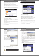
4. The Wireless Settings screen (Figure 7-11) will appear. If you chose
Infrastructure Mode, go to Step 5 now. If you chose Ad-Hoc Mode, select
the correct operating channel for your network from the Channel drop-
down menu. Then, select the Network Mode from the drop-down menu.
Click the Next button, and go to Step 5. Click the Back button to change
any settings.
Channel - The channel you choose should match the channel set on the
other devices in your wireless network. If you are unsure about which chan-
nel to use, select the default channel (Channel 6).
Network Mode - Select Mixed Mode, and both Wireless-G and Wireless-
B computers will be allowed on the network, but the speed will be reduced.
Select G-Only Mode for maximum speed, but no Wireless-B users will be
allowed on the network.
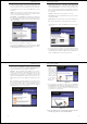
5. The Network Setting screen (Figure 7-12) will appear.
If your network has a DHCP server, click the radio button next to Obtain
an IP address automatically (DHCP). Click the Next button to continue,
or click the Back button to return to the previous screen.
22
If your network does not have a DHCP server, click the radio button next to
Specify the IP address. Enter an IP Address, Subnet Mask, Default
Gateway, and DNS appropriate for your network. Enter each address in this
format: xxx.xxx.xxx.xxx (the x’s represent the numbers that make up each
address). You must specify the IP Address and Subnet Mask on this screen.
If you are unsure about the Default Gateway and DNS addresses, then leave
these fields alone.
IP Address - This IP Address must be unique to your network.
Subnet Mask - The Adapter’s Subnet Mask must be the same as your wired
network’s Subnet Mask.
Default Gateway - Enter the IP address of your network’s Gateway here.
DNS - Enter the DNS addresses of your Ethernet (wired) network here.
Click the Next button to continue or the Back button to return to the previ-
ous screen.
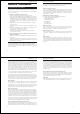
6. The Security Settings screen (Figure 7-13) will appear. Enable or disable
Wired Equivalent Privacy (WEP) encryption for your wireless network. If
you enable WEP, enter a Passphrase or WEP key. Click the Next button to
continue or the Back button to return to the previous screen.
Figure 7-12
Figure 7-11
Wireless-G Notebook Adapter
25
Instant Wireless
®
Series
WEP (Disabled/64 bits WEP/128 bits WEP) - If you do not want to use
WEP encryption, choose Disabled. To use WEP encryption (recommended
to increase network security), select 64 bits or 128 bits WEP from the
drop-down menu, and enter either a Passphrase or WEP key.
Passphrase - Instead of manually entering WEP keys, you can enter a
Passphrase, so that a WEP key is automatically generated. It is case-sensi-
tive and should not be longer than 16 alphanumeric characters. This
passphrase must match the passphrase of your wireless network and is com-
patible with other Linksys wireless products only. (If you have any non-
Linksys wireless products, enter the WEP key(s) manually on those prod-
ucts.)
Key 1 - This WEP key must match the WEP key of your wireless network.
If you are using 64-bit WEP encryption, then the key must consist of exact-
ly 10 hexadecimal characters. If you are using 128-bit WEP encryption,
then the key must consist of exactly 26 hexadecimal characters. Valid hexa-
decimal characters are “0” to “9” and “A” to “F”.
24
7. The Confirm New
Settings screen
(Figure 7-14) will
appear. To save the
new settings, click
the Ye s button. To
cancel the settings
and return to the
Profiles screen,
click the No button.
To edit the new set-
tings, click the
Back button.
8. The Congratulations screen (Figure 7-15) will appear next. Click Activate
new settings now to implement the new settings immediately and return to
the Link Information screen. Click Activate new settings later to keep the
current settings active, and return to the Profiles screen so that you can edit
your profile or create another profile.
You have successfully created a connection profile. Click the X (Close) but-
ton in the upper right corner to exit the WLAN Monitor.
Figure 7-14
Figure 7-15
Figure 7-13