
User's Manual


RK-Wi.232FHSS-25-FCC Rapid Development Kit User’s Manual
© 2002-6 Radiotronix Inc, all rights reserved - 7 - 3/27/2006
4 Using the Evaluation Software
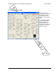
4.1 Setting Register Values.
On both the Volatile and Non-Volatile pages, the registers are labeled by function. To set a register value,
select the value from the options available for that register and click the “Write” button. To perform a read
of that register, simply click the “Read” button. Descriptions of the register functions can be found in the
Wi.232FHSS Users Manual.
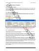
4.2 Diagnostic Mode Commands
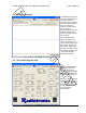
There are a special class of commands available through the evaluation software. These controls are
accessed by clicking the “Show” button in the “Diagnostic Window” group located on the “Volatile
Registers” page as seen below.
These commands place the module into special diagnostic modes that can be used to test the module’s
performance, or to activate the transmitter for RF testing purposes. NOTE: once a module executes a
diagnostic command, it should be reset or have the power cycled to return to normal operation.
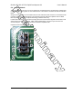
4.2.1 Transmit Diagnostic
Transmit Diagnostic consists of the controls located in the “Transmit Diagnostic” group. The transmit
diagnostic group is broken into two smaller sub-groups.
The left side is used to observe static transmitter characteristics- that is, when the “TX 1-Channel Diag”
button is clicked, it stops the module from hopping frequencies. The radio buttons on the left allow quick
selection of the transmitter’s channel/frequency. Once activated, a “…1010101010101…” bit pattern is
transmitted for bit error testing or RF carrier analysis. This single-channel transmit diagnostic mode can
be used with the receive diagnostic.
The right side is used to observe dynamic transmitter characteristics. Dynamic transmitter operation
allows the module to hop frequencies as it transmits. The “Hop Set” radio button selects the hop
sequence (analogous to a channel, values are 0-5) to be used when hopping. Dynamic transmitter mode
cannot be used to provide a carrier for the Receive Diagnostic. Clicking the “Tx FHSS Diag” button sends
the new hopping sequence value to the module and activates the transmitter. The “Start Hop” and “Stop
Hop” buttons start and stop the diagnostic hopping, respectively.
In the middle, the light-orange colored box controls the power and modulation characteristics of the
transmitter. For the FCC-Wi.232FHSS-25™, there are four power settings of increasing intensity: Low,
Mid-Low, Mid-High, and High. The “Mod Off” and “Mod On” buttons switch the carrier’s modulation off
and on, respectively.