
User's Manual


Page 2 Page 3
1. Characterized, but not tested
Notes
ELECTRICAL SPECIFICATIONS
Parameter Designation Min. Typical Max. Units Notes
POWER SUPPLY
Operating Voltage V
CC
2.1 3.0 3.6 VDC –
Supply Current I
CC
–3.4–mA–
Power-Down Current I
PDN
–5.0–nA1
TRANSMITTER SECTION
Transmit Frequency Range: F
C
CMD-HHTX-315 – 315 – MHz –
CMD-HHTX-418 – 418 – MHz –
CMD-HHTX-433 – 433.92 – MHz –
Center Frequency Accuracy – -50 – +50 kHz –
ENVIRONMENTAL
Operating Temperature Range – -30 – +70 °C 1
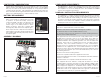
SETTING THE TRANSMITTER ADDRESS
The Full-Size Handheld transmitter allows
the selection of one of 256 unique
addresses. All transmitters are supplied set
to the same address. To avoid contention
with other units or to create unique
relationships, the address can be changed.
This is accomplished using internal DIP
switches as shown. The switches are
accessed by removing the rear cover as for
battery replacement.
If the switch is on, the address line is
connected to ground, otherwise it is
floating. The receiver’s address must match
exactly in order for the units to communicate. Application Note AN-00300
describes in detail how to set the address to match any of the receivers offered
by Linx. This note can be found in the Support section of the Linx web site,
www.linxtechnologies.com.
CMD-HHTX BUTTON ASSIGNMENTS
This diagram illustrates the relationship between the button locations and
encoder data lines.
D7 D6
D5 D4
D3 D2
D1 D0
Figure 3: CMD-HHTX-*** Button Assignments
ON OFF
A7 = 1
A6 = 2
A5 = 3
A4 = 4
A3 = 5
A2 = 6
A1 = 7
A0 = 8
Figure 2: DIP Switch Assignments
THEORY OF OPERATION
The CMD-HHTX-*** Full-Size Handheld transmitter combines the LR Series
transmitter and an antenna with an on-board Holtek HT640 encoder IC to form a
simple, yet highly reliable, RF remote-control transmitter. The LR Series
transmitter is a low-cost, high-performance synthesized ASK / OOK transmitter.
The transmitter’s synthesized architecture delivers outstanding stability and
frequency accuracy, while minimizing the effects of antenna port loading and
mismatching. This reduces or eliminates frequency pulling, bit contraction, and
other negative effects that are common to SAW-based transmitter architectures,
providing a significantly higher level of performance and reliability.
When a button is pressed on the transmitter, power is applied to the internal
circuitry and the encoder IC is enabled. The encoder detects the logic states of
the address lines and button data lines. These states are formatted into a three-
word transmission cycle that continues until the button is released. The encoder
data is used to modulate the transmitter, which, through the antenna, conveys
the data into free space. On the receiver side, a decoder IC or custom
microcontroller is used to check the transmitter’s address bits against the
address settings of the receiving device. If a match is confirmed, the decoder’s
outputs are set to replicate the transmitter’s button states. These outputs can
then be used to activate external circuitry required by the application.
The transmitter is compatible with several Linx receiver products, including the
LR, KH2, LT, and OEM product families. When the transmitter is combined with
an LR Series receiver and the HT658 decoder chip, ranges of up to 750 feet are
possible. Applications operating over shorter distances will also benefit from the
increased link reliability and superior noise immunity provided by the LR Series
receiver.