
User's Manual

Page 3Page 2
THEORY OF OPERATION
The CMD-KEY#-xxx Keyfob Command Unit combines the LR Series transmitter
with an on-board Holtek HT640 encoder IC to form a simple, yet effective, RF
remote-control transmitter. The LR transmitter is a low-cost, high-performance
synthesized ASK/OOK transmitter. The transmitter’s synthesized architecture
delivers outstanding stability and frequency accuracy while minimizing the effects
of antenna port loading and mismatching. This reduces or eliminates frequency
pulling, bit contraction, and other negative effects that are common to SAW-
based transmitter architectures, providing a significantly higher level of
performance and reliability.
When a button is pressed on the remote unit, power is applied to the internal
circuitry and the encoder IC is enabled. The encoder then detects the logic states
of the address lines and button data lines. These states are formatted into a
three-word transmission cycle that continues until the button is released. The
encoder data is used to modulate the transmitter, which, through the antenna,
conveys the data into free space. On the receiver side, a decoder IC or custom
microcontroller is used to check the transmitter's address bits against the
address settings of the receiving device. If a match is confirmed, the decoder’s
outputs are set to replicate the transmitter’s button states. These outputs can
then be used to activate external circuitry required by the application.
The transmitter is compatible with several Linx receiver products, including the
LC, LR, KH, and OEM product families. For applications where range is critical,
the LR Series receiver is the best choice due to its outstanding sensitivity. When
the keyfob transmitter is combined with an LR Series receiver and the HT658
decoder chip, ranges up to 1000 feet are possible. Applications operating over
shorter distances will also benefit from the increased link reliability and superior
noise immunity provided by the LR Series receiver.
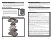
SETTING THE TRANSMITTER ADDRESS
The keyfob allows the selection of one
of 1024 unique addresses. All keyfobs
are supplied set to the same address.
To avoid contention with other units or
to create unique relationships, the
address can be changed. This is
accomplished by cutting the traces with
a sharp object, such as an X-Acto knife.
The traces are accessed by removing
the rear cover.
If the trace is intact, the address line is
connected to ground, otherwise it is
floating. The receiver's address must match exactly in order for the units to
communicate. Application Note AN00300 describes in detail how to set the
address to match any of the receivers offered by Linx. This note can be found in
the Support section of the Linx web site.
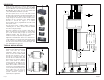
BUTTON ASSIGNMENTS
The keyfob is available in five unique button configurations. Those configurations
and the corresponding switch numbers are shown in the figure below. The table
shows which encoder data line has been assigned to each switch. When a
button is pressed, the data line will go high, causing the corresponding data line
on the decoder to go high if the addresses match.
S4
S2
S1
S3S5
S5
S2
S5
S4
S4
S2
S4
S1
S3
S2
Figure 3: CMD-KEY#-xxx Button Assignments
Figure 2: DIP Switch Assignments
Button Data Line
S1 D0
S2 D1
S3 D2
S4 D3
S5 D4
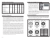
ELECTRICAL SPECIFICATIONS
PPaarraammeetteerr DDeessiiggnnaattiioonn MMiinn.. TTyyppiiccaall MMaaxx.. UUnniittss NNootteess
POWER SUPPLY
Operating Voltage V
CC
2.1 3.0 3.6 V
DC
–
Supply Current I
CC
–
3.4
–
mA
–
Power-down Current I
PDN
–
5
–
nA
1
TRANSMITTER SECTION
Transmit Frequency Range F
C
CMD-KEY#-315
–
315
–
MHz
–
CMD-KEY#-418
–
418
–
MHz
–
CMD-KEY#-433
– 433.92 –
MHz
–
Center Frequency Accuracy
–
-50
–
+50 kHz
–
ENVIRONMENTAL
Operating Temperature Range – -40 – +85
°C1
1. Characterized, but not tested.
Notes