
User's Manual

V
CC
G
N
D
B1
T
OUC
HPA
D
S5
T
OUC
HPA
D
S4
T
OUC
HPA
D
S3
T
OUC
HPA
D
S2
T
OUC
HPA
D
S1
V
CC
V
CC
CU
T TRA
C
E F
OR
ADDRESS SELECT
G
N
D
390k
R4
G
N
D
HT
6
4
0
U1
24
V
CC
23
D
0
22
A
9
21
A8
20
A7
1
9
A
6
1
8
A
5
17
A4
1
6
A
3
1
5
A2
14
A1
1
3
A
0
12
G
N
D
11
OSC1
1
0
OSC2
9
TE
8
D
OUT
7
D7
6
D
6
5
D
5
4
D4
3
D
3
2
D2
1
D1
V
CC
V
CC
G
N
D
DATA IN
G
N
D
IAD
J/
V
CC
RF
OUT
G
N
D
VC
C
PDN
TXM
-
XXX
-
LR
G
N
D
G
N
D
G
N
D
R1
S
et For F
CC
Com
p
lianc
e
Page 6 Page 7Page 7
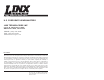
Figure 7: Schematic Diagram
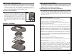
RECEIVERS
There are four options for receivers within the Linx
product line. The first option is to use one of the OEM
Function Modules, such as the Relay Module or the AC
Wall Module. These items are also pre-certified and
can be immediately included in a product.
The other options are to use one of the Linx receiver
modules. The signal sent by the Keyfob transmitter can
be received by the LC Series receiver module or, for
longer range, the LR Series receiver module. These
modules can be connected to the Holtek HT658
decoder to decode the signal or a custom
microcontroller can be programmed to decode it and
take specific action.
The KH Series offers a slightly simpler solution by
combining the LC Series receiver and the HT658
decoder in a single package.
The basic operation for the system is that when a
button is pressed on the transmitter, a corresponding
pin on the decoder will go high (as long as the
addresses match). This can then be connected to
whatever circuitry is required by the application
Application Note AN00300 discusses in detail how to
set the addresses on all of the units. Data guides for all
of the receivers, the HT640 encoder, and the HT658
decoder can be found on the Linx Technologies web
site, www.linxtechnologies.com.
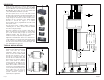
TYPICAL APPLICATIONS
The outstanding sensitivity of the LR
Series receiver offers the best range
when used with the keyfob
transmitter. When using the LR
Series receiver, the Holtek HT658
decoder chip should be used to
decode the received signal. This
decoder has ten address lines that
must match the keyfob address
lines. A DIP switch is commonly
used to set these, but they can also
be hardwired. If the address lines
match, when a button on the keyfob
is pressed a corresponding data line
on the decoder (D0-D4) will go high.
These data lines can then be
connected to external circuitry to
perform whatever function is
required by the application.
F
C
TN-RLY4-xx
x
F
C
TN-WALL-xx
x
RXM-xxx-L
C
-
S
RXM
-
xxx
-
LR
RXD
-
xxx
-
KH
G
N
D
R1
390k
G
N
D
G
N
D
V
CC
V
CC
D1
1
D2
2
D
3
3
D4
4
D
5
5
D
6
6
D7
7
VT
8
DIN
9
OSC1
1
0
OSC2
11
G
N
D
12
A
0
1
3
A
1
14
A
2
1
5
A
3
1
6
A4
17
A
5
1
8
A
6
1
9
A7
2
0
A
8
21
A
9
22
D
0
2
3
V
CC
24
HT
658
N
C
1
N
C
2
N
C
3
G
N
D
4
V
CC
5
PDN
6
R
SSI
7
DATA
8
N
C
9
N
C
1
0
N
C
11
N
C
12
N
C
1
3
N
C
14
G
N
D
1
5
ANT
1
6
RXM-XXX-LR-
S
G
N
D
Figure 6: LR Receiver and HT658 Schematic