
User's Manual


V
CC
GND
B1
BAT-LINX2032
G
N
D
R4
1
00K
G
N
D
S1
T
OUC
HPA
D
S2
T
OUC
HPA
D
S3
T
OUC
HPA
D
S4
T
OUC
HPA
D
S5
T
OUC
HPA
D
D
6
1
D7
2
SEL
_
BAUD
0
3
SEL
_
BAUD
1
4
G
N
D
5
G
N
D
6
G
N
D
7
TX_CNT
L
8
DATA
_
OU
T
9
M
O
DE
_
IN
D
1
0
C
REATE
_
ADD
R
11
S
EN
D
1
2
D
0
1
3
D1
14
V
CC
1
5
V
CC
1
6
D2
17
D
3
1
8
D4
1
9
D
5
2
0
U2
LI
C
AL-EN
C
-M
S
V
CC
V
CC
V
CC
V
CC
G
N
D
G
N
D
G
N
D
G
N
D
S6
S
W-P
B
GN
D
GN
D
GN
D
GN
D
GN
D
G
N
D
G
N
D
R2
N
S
R
3
1
00K
R
5
1
00K
R
6
1
00K
R1
0
1
00K
R
9
1
00K
R7
1
00K
R
8
1
00K
GN
D
GN
D
G
N
D
R11
2
00
D1
STAT
_
IN
D
GND
R1
GND
1
DATA IN
2
GND
3
IADJ/VCC
4
RF OUT
5
GND
6
VCC
7
PDN
8
TX1
LRTX
GND
GND
ANT1
ANTENNA
Page 6 Page 7Page 7
Figure 7: OTX-***-HH-KF#-MS Schematic Diagram
TYPICAL APPLICATION
The signal sent by the Keyfob transmitter can be
received by the LC Series receiver module or the LR
Series receiver module. The outstanding sensitivity of
the LR Series receiver offers the best range when used
with the Keyfob transmitter. The receiver module is
then connected directly to the MS Series decoder,
which will decode the transmitted signal.
The basic operation for the system is that when a
button is pressed on the transmitter, a corresponding
pin on the decoder will go high. This can then be
connected to external circuitry to perform whatever
function is required by the application.
The decoder must learn the transmitter’s address
before they can work together. This is done by taking
the LEARN line on the decoder high, typically with a pushbutton. The
MODE_IND line will start switching (if an LED is attached, this will cause it to
flash) indicating that the decoder is in Learn Mode. Press any of the buttons on
the transmitter to initiate a transmission. Take the LEARN line high again to exit
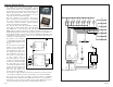
Learn Mode and the system is ready for use. The figure below shows a
schematic for a typical application.
The Keyfob is set to 9600bps,
so SEL_BAUD0 should be tied
to Vcc and SEL_BAUD1 tied to
ground.
The decoder has several unique
features, such as Latch Mode,
Receiver Control, and TX_ID.
If the LATCH line is tied to Vcc,
the outputs will go high on the
first transmission, then low on
the second. It is shown tied low,
so the outputs will be
momentary (high for as long as
a signal is received instructing
the decoder to make them high).
The RX_CNTL line can be
connected to the PDN line of the
receiver and the decoder will
activate the receiver with a 10%
duty cycle This reduces the
average current consumption of
the system. The adjacent figure shows it tied to ground, but to use this feature,
connect the RX_CNTL line of the decoder directly to the receiver’s PDN line.
The TX_ID line will output a number associated with the originating
transmitter/encoder. Application Note AN00156 shows how to use this feature.
Data guides for the receivers, the MS encoder, and the MS decoder can be
found on the Linx Technologies web site, www.linxtechnologies.com.
G
N
D
G
N
D
V
CC
N
C
1
N
C
2
N
C
3
G
N
D
4
V
CC
5
PDN
6
R
SSI
7
DATA
8
N
C
9
N
C
1
0
N
C
11
N
C
12
N
C
1
3
N
C
14
G
N
D
1
5
ANT
1
6
RXM-XXX-LR-
S
22
0
D
6
D7
SEL
_
BAUD
0
SEL
_
BAUD
1
G
N
D
G
N
D
LAT
CH
RX
_
CNT
L
TX
_
I
D
MODE_IN
D
D
5
D4
D
3
D2
V
CC
V
CC
D
1
D
0
DATA
_
I
N
LEARN
1
2
3
4
5
6
7
8
9
1
0
11
12
1
3
14
1
5
1
6
17
1
8
1
9
2
0
LI
C
AL-DE
C
-M
S001
V
CC
G
N
D
G
N
D
V
CC
Figure 6: LR Receiver and MS Decoder Schematic
RXM-***-LR
LICAL-DEC-MS001