P���� T����� J��� INSTALL MANUAL Rev: 09.29.
Safety and System Information Safety Information The “WARNING” symbol above is a sign that an installation procedure has a safety risk involved and may cause death or serious injury if not performed safely and within the parameters set forth in this manual. Always wear eye protection when performing this installation procedure. Other safety equipment to consider would be hearing protection, gloves, and possibly a full face shield, depending on the nature of the installation procedure.
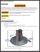
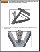
The coach MUST be supported per OEM specifications before working underneath. Failure to do so may result in death or serious injury. Installation 1. Carefully slide the jack leg (Fig. 2A) through the hole in the coupler (Fig. 2B) on the travel trailer “A” frame (Fig. 2C). Fig. 2 A C B 2. Align the three (3) holes in the Power Tongue Jack mounting plate (Fig. 3A) with the three (3) holes in the coupler (Fig. 3B). Fig. 3 A Rev: 09.29.
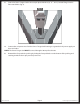
3. Secure the Power Tongue Jack to the coupler plate with three (3) 3⁄8" - 16x1; Serrated Flange Grade 5 Zinc coated bolts (Fig. 4). Fig. 4 4. Connect the red power wire from the Power Tongue Jack housing to a grounded 12V power supply on the travel trailer. NOTE: The Power Tongue Jack MUST be wired through a 30 amp fused circuit. 5. Reattach the foot pad to the jack leg by sliding the foot pad back over the bottom of the jack leg and securing it with the clevis pin previously removed. Rev: 09.29.
Notes Rev: 09.29.
The contents of this manual are proprietary and copyright protected by Lippert Components, Inc. (“LCI”). LCI prohibits the copying or dissemination of portions of this manual unless prior written consent from an authorized LCI representative has been provided. Any unauthorized use shall void any applicable warranty. The information contained in this manual is subject to change without notice and at the sole discretion of LCI. Revised editions are available for free download from www.lci1.com.