3 X 3 SLIDEOUT SYSTEM OPERATION AND SERVICE MANUAL
TABLE OF CONTENTS SYSTEM……………………………………………........….…..3 Warning…………………………………........……....3 Description………………………………........……..3 Prior to Operation…………………….......………4 OPERATION…………………………………........……………5 Main Components....................................... 5 Mechanical....................................... 5 Electrical.......................................... 6 Operating System....................................... 7 Extending Slideout........................... 7 Retracting Slideout................
SYSTEM WARNING FAILURE TO ACT IN ACCORDANCE WITH THE FOLLOWING MAY RESULT IN SERIOUS PERSONAL INJURY OR DEATH. The Lippert 3 x 3 Slideout System is intended for the sole purpose of extending and retracting the slideout room. Its function should not be used for any other purpose or reason than to actuate the slideout room. To use the system for any reason other than what it is designed for may result in damage to the coach and/or cause serious injury or even death.
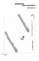
Disassembly of the motor voids the warranty. Mechanical portions of the slideout system are replaceable. Contact Lippert Components, Inc. to obtain replacement parts. PIVOT RAIL– see Fig. 1 page 5 The Lippert 3 x 3 Slideout System has three basic assemblies: 1. Outer Rail –Flange welds to frame of coach. Flange is mounted to the outside end of the outer rail. The inside end of the outer rail is welded to frame also. 2.
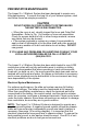
OPERATION MAIN COMPONENTS MECHANICAL Fig.
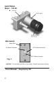
ELECTRICAL Motor - 12V DC Gear Box 12 VDC Motor Electronic Brake (Not Shown) Wall Switch Switch Plate “IN” Slideout Operation SPOT Momentary Switch “OUT” Slideout Operation Fig. 3 CAUTION! – The wall switch operates on high voltage. Exercise caution when servicing.
OPERATING SYSTEM WARNING FAILURE TO ACT IN ACCORDANCE WITH THE FOLLOWING MAY RESULT IN SERIOUS PERSONAL INJURY OR DEATH. ALWAYS MAKE SURE THAT THE SLIDEOUT ROOM PATH IS CLEAR OF PEOPLE AND OBJECTS BEFORE AND DURING OPERATION OF THE SLIDEOUT ROOM. ALWAYS KEEP AWAY FROM THE SLIDE RAILS WHEN THE ROOM IS BEING OPERATED. THE GEAR ASSEMBLY MAY PINCH OR CATCH ON LOOSE CLOTHING CAUSING PERSONAL INJURY. INSTALL TRANSIT BARS (IF SO EQUIPPED) ON THE SLIDEOUT ROOM DURING STORAGE AND TRANSPORTATION.
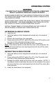
C B Fig. 4 MANUAL OPERATION WARNING! Always disconnect battery from system prior to manually operating system. Failure to disconnect battery can cause electricity to backfeed through the motor and cause serious damage to the system as well as void the warranty. 1. Prior to Manual Operation, be sure to clear any obstruction from the slideout area that may impede the extension or retraction of the slideout room, including any transit bars. 2. Locate Slideout Motor and drive tubes under coach. 3.
PREVENTATIVE MAINTENANCE The Lippert 3 x 3 Slideout System has been designed to require very little maintenance. To ensure the long life of your slideout system, read and follow these few simple procedures. CAUTION DO NOT WORK ON YOUR SLIDEOUT SYSTEM UNLESS THE BATTERY IS DISCONNECTED. • When the room is out, visually inspect the Inner and Outer Rail Assemblies. Refer to Fig. 1 for location of inner rail assemblies.
Mechanical Maintenance Although the system is designed to be almost maintenance free, actuate the room once or twice a month to keep the seals and internal moving parts lubricated. Check for any visible signs of external damage after and before movement of the travel trailer. NOTE: For long-term storage: It is recommend that the room be closed (retracted). SERVICE TROUBLESHOOTING The Lippert 3 x 3 Slideout System is only one of four interrelated slideout room system components.
ROOM ADJUSTMENT The Lippert 3 x 3 Slideout System can be timed and fine-tuned for optimum performance. In the event the travel of either side of this tworail system should be out of time, follow this process for re-timing the slide-out room. Note: When addressing issues regarding your slide-out room, remember to relay the information from the OUTSIDE of the coach. This note will help to standardize the information needed to be relayed to a service station or technical service at LCI.
TROUBLESHOOTING CHART The following troubleshooting chart outlines some common problems, their causes and possible corrective actions. When reference is made to a “Power Unit,” the term includes the motor and the actuator as a complete unit. All Power Units are shipped from the factory with a serial number and date code, which should be given to the service technician when asking for assistance.
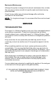
Switch related problems: • If room moves opposite from what the switch plate indicates, reverse the motor wires on the back of the switch (refer to the wiring diagram page 16). Wire size must be 10ga. Min. WARNING! – HIGH VOLTAGE • • If a gear is stripped, the entire gearbox must be replaced. If the room does not seal fully, refer to page 13. TROUBLESHOOTING – MOTOR Before attempting to troubleshoot the Motor, make sure an adequate power source is available.
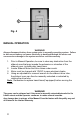
- MOTOR BLACK RED 10 GA WIRE MINIMUM RED GREEN MOTOR MOTOR OUT IN SWITCH CAUTION! HIGH VOLTAGE BATTERY (-) WHITE BATTERY (+) BLACK BATTERY (-) WHITE Fig.
ORDERING PARTS To assist the customer service when ordering parts, please provide the following information: 1. Your Name 2. Company Name 3. Phone Number 4. Shipping Address 5. Billing Address 6. Purchase Order Number 7. Coach A. Serial # and/or VIN # B. Make C. Model 8. Part Number 9. Description 10. Quantity Please take your coach to an authorized service center for repairs.