IN-WALL™ S����-��� OWNER'S MANUAL Rev: 11.21.
TABLE OF CONTENTS System and Safety Information Safety Information Prior to Operation Operation Extending Slide-out Room Retracting Slide-out Room Troubleshooting Controller Overview (B Version) Controller Overview (C-2 Version) Electronic Manual Override Extend and Retract Switch Connections Power and Ground Connections at the Controller Error Codes Low Voltage Obstructions Checking Fuses Motors and Harnesses Resynchronizing the Slide-out Motors IN-WALL™ Slide-out Assembly IN-WALL™ Slid
Prior to Operation 1. 2. 3. 4. Park the coach on the most level surface available. Actuate the leveling or stabilizing systems to ensure coach will not move during operation of slide-out system. Be sure battery is fully charged. Be sure to keep all persons and pets clear of slide-out system during operation. NOTE: Install transit bars (if so equipped) on the slide-out room during storage and transportation.
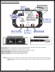
Troubleshooting Controller Overview (B Version) Controller Version Fig. 2 Green LED Red LED Power Connection Motor 1 Connector Switch Connection Fig. 3 - Controller Connections Motor 2 Connector Fig. 4 - End of Motor Harness Status LEDs: 2 LEDs, 1 green and 1 red, are provided to indicate current controller status and faults. Power Connection: 12V DC input. Unit will operate from 8V DC to 18V DC. Switch Connection: Spade connection for the switch wiring.
Controller Overview (C-2 Version) Controller Version Mode Button Fig. 5 Green LED Red LED Power Connection Motor 1 Connector Switch Connection Fig. 6 - Controller Connections Motor 2 Connector Fig. 7 - End of Motor Harness Status LEDs: 2 LEDs, 1 green and 1 red, are provided to indicate current controller status and faults. Mode Button: Used to engage the electronic manual override. Power Connection: 12V DC input. Unit will operate from 8V DC to 18V DC.
Electronic Manual Override (Controllers C-1 and C-2 Only) NOTE: See (Fig. 5) for locations of the mode button and LEDs. 1. Press the mode button on the controller six times and hold on the seventh for five seconds to enter electronic manual override mode. 2. Use the extend/retract switch to move both motors in or out. NOTE: Over-current and short circuit detection are disabled. Electronic manual override provides 12V directly to both motors. 3.
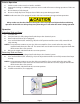
Obstructions Check outside the RV for possible obstructions: tree, post, car, etc. Check inside the RV for any obstructions: luggage, furniture, open cabinets, etc. Also, check for smaller objects that may be wedged under the floor or in the sides of unit. Remove obstructions before proceeding. Checking Fuses The Lippert IN-WALL™ Slide-out requires a minimum of a 30-amp fuse. Check the 12-volt fuse box for blown fuses, and replace any if necessary.
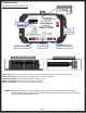
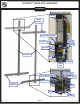
IN-WALL™ SLIDE-OUT ASSEMBLY SLIDE-OUTS Upper Bearing Block Detail Motor Upper Gear Rack Upper Bearing Block Coupler Gear Rack Shoe Spur Gear H-Column Gib V-Roller Torque Shaft Lower Bearing Block Detail Lower Bearing Block Torque Shaft Gear Rack Spur Gear Lower Gear Rack Shoe Gib V-Roller Rev: 11.21.
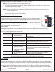
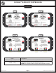
IN-WALL™ SLIDE-OUT CONTROLLERS SLIDE-OUTS Rev B Rev C-1 Rev C-2 8 Amp Part # 211852 - Rev B, Rev C-1, Rev C-2 326876 - 8 amp Rev: 11.21.2014 Description Dual Motor Synchronous Velocity Slide Controller Dual Motor Synchronous Velocity Slide Controller NOTE: This controller will not replace other controller versions.
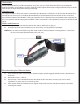
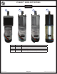
IN-WALL™ SLIDE-OUT MOTORS SLIDE-OUTS B A Callout A B C D Rev: 11.21.
IN-WALL™ SLIDE-OUT COMPONENTS SLIDE-OUTS A B C D E Callout A B C D E Rev: 11.21.2014 Part # 238744 238990 247768 229755 238991 229756 238992 229758 229759 241834 241835 241836 258760 Description 5 ft. Controller to Motor Harness 10 ft. Controller to Motor Harness 15 ft. Controller to Motor Harness 20 ft. Controller to Motor Harness 25 ft. Controller to Motor Harness 30 ft. Controller to Motor Harness 35 ft. Controller to Motor Harness Harness Connectors 5 Wires Harness Connectors 3 Wires 5 ft.
IN-WALL™ SLIDE-OUT COMPONENTS C B A E G F D I H Callout A B C D E F G H I Rev: 11.21.
IN-WALL™ SLIDE-OUT COMPONENTS B A D F E G I H Callout A B C D E F G H I Rev: 11.21.
IN-WALL™ SLIDE-OUT COMPONENTS SLIDE-OUTS A B C E D F I G Callout A B C D E F G H I Rev: 11.21.
The contents of this manual are proprietary and copyright protected by Lippert Components, Inc. (“LCI”). LCI prohibits the copying or dissemination of portions of this manual unless prior written consent from an authorized LCI representative has been provided. Any unauthorized use shall void any applicable warranty. The information contained in this manual is subject to change without notice and at the sole discretion of LCI. Revised editions are available for free download from www.lci1.com.