INSTALLATION & OPERATION MANUAL IT200N REV. D Remote Rate Indicator DOC#: MN-200N-D.
Sponsler, Inc. IT200N Remote Rate Indicator pg. 2 DOC#: MN-200N-D.DOC TABLE OF CONTENTS PAGE # SPECIFICATIONS........................................................................................................................... 3 INTRODUCTION ............................................................................................................................. 4 General ............................................................................................................................
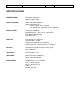
Sponsler, Inc. IT200N Remote Rate Indicator pg. 3 DOC#: MN-200N-D.DOC SPECIFICATIONS TEMPERATURE: Operating -40 to 85°C Storage –65 to 125°C INPUT VOLTAGE: Internal AA Lithium Battery Battery Operating Life – Rate Function: 3 years typical (Assuming 24 hr. operation at max. flowrate) INPUT SIGNAL: Frequency 0-2500 Hz Amplitude 25 mV – 36V sine or squarewave Sensitivity field adjustable Impedance 10K DISPLAY: LCD, 6 Digit .
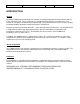
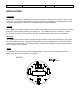
Sponsler, Inc. IT200N Remote Rate Indicator pg. 4 DOC#: MN-200N-D.DOC INTRODUCTION General The Model IT200N Industrial Remote Rate Indicator is a battery powered device that provides flow rate in any engineering unit. Rate is displayed via a 6-digit liquid crystal display. Selection of the reset function is accomplished externally by a magnetic field. This particular feature retains the unit's integrity permitting complete operational control in hazardous environments.
IT200N Remote Rate Indicator Sponsler, Inc. pg. 5 DOC#: MN-200N-D.DOC INSTALLATION Inspection All units are completely assembled, inspected and tested at the factory prior to shipment. Upon receipt of the unit, a visual inspection should be conducted to detect any impropriety or damage that may have occurred during shipment. Report any discrepancy to the factory immediately.
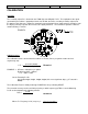
IT200N Remote Rate Indicator Sponsler, Inc. pg. 6 DOC#: MN-200N-D.DOC CALIBRATION Sensitivity The sensitivity adjust R1 is located on the IT200I (Input and Digital) P.C.B. The amplitude of the signal generated by the turbine is proportional to the rate of flow; therefore, sensitivity should be adjusted at the lowest usable flow rate. Rotate R1 completely counterclockwise then slowly rotate R1 clockwise until the display correctly responds then increase R1 slightly clockwise.
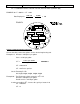
IT200N Remote Rate Indicator Sponsler, Inc. pg. 7 DOC#: MN-200N-D.DOC C.F. = Calibration Factor as entered in S1-S5 (S5 is the most significant digit) EXAMPLE #2: F = 500 Hz C.F. = 250 Rate Displayed = 500 x 60 250 = 30,000 250 = 120 FIGURE 3 Change of Calibration Engineering Units Assume that liters rather than gallons are the desired engineering unit. Example # 3: K-Factor = 250 pulses per gallon Liters = 3.785 per gallon C.F. = Pulses per Gallon Units per Gallon Formula 3 C.F. = 250/3.
Sponsler, Inc. IT200N Remote Rate Indicator pg. 8 DOC#: MN-200N-D.DOC On the Factoring P.C.B.: Set S1@3, S2, 3, 4, 5@0 Example #5: The engineering unit is ACF (FT3) K-Factor = 250 pulses per gallon ACF = .13369 per gallon C.F. = .250/.13669 C.F. = 1870 On the Factoring P.C.B.: Set S1@0, S2@7, S3@8, S4@1, S5@0 Example #6: Desired Engineering Unit is ACF x 10 K-Factor = 250 pulses per gallon ACF = .13369 per gallon In order to establish x 10, decrease ACF/gal by a factor of 10 C.F. = 250/.
Sponsler, Inc. IT200N Remote Rate Indicator pg. 9 DOC#: MN-200N-D.DOC New C.F. = 50/52 x 250 = .96 x 250 = 240 On the Factoring P.C.B.: Set S1@0, S2@4, S3@2, S4@0, S5@0 In the above example, .96 denotes that the meter is operating 4% slow. Multiplying by the present C.F. (.250) by the Displayed : Actual Ratio (.96) effectively reduces the error by decreasing the C.F. by 4%. Rate Display Considerations The displayed rate is limited to a maximum of 30,000.
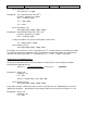
IT200N Remote Rate Indicator Sponsler, Inc. pg. 10 DOC#: MN-200N-D.DOC FUNCTION SELECTION Reset Function Reset is valid only to load a new calibration factor. Reset is initiated externally by placing a magnet in the proximity of reset S6 located on the Display P.C.B. and indicated on the enclosure label as ‘RESET’. FIGURE 4 MISCELLANEOUS Factored Digital Pulse Output This signal output is an open drain configuration that can sink 1A continuously.
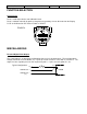
IT200N Remote Rate Indicator Sponsler, Inc. pg. 11 DOC#: MN-200N-D.DOC Battery Replacement The battery is located on the Mounting P.C.B. and inserts into 2 sockets. When installing the battery, it is imperative to OBSERVE POLARITY. Simply pull the 3-board stack (See Figure #5) out of the enclosure, install the battery and reinsert the board stack. The display will be all zeros. FIGURE 5 This figure illustrates the removal of the 3-board stack from the condulet.
Sponsler, Inc. IT200N Remote Rate Indicator pg. 12 FIGURE 6 ©2009 Pub. No. MN-200N-D (09/09) DOC#: MN-200N-D.