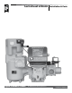
LectroCount LCR 600 Liquid Controls Group An IDEX Fluid & Metering Business Installation & Parts Installation: EM150-10
Table of Contents Introduction Bill of Materials Safety Procedures .................................................... 3 ESD Protection.......................................................... 4 Specifications ........................................................... 5 Dimensions............................................................... 6 LectroCount LCR 600 Overview............................... 7 Meter System Overview............................................ 8 External Components.........
Safety Procedures Be Prepared ! WARNING • Before using this product, read and understand the instructions. • All work must be performed by qualified personnel trained in the proper application, installation, and maintenance of equipment and/or systems in accordance with all applicable codes and ordinances.
ESD Protection Potential Damages Caused by Exposure to ESD To prevent electrostatic discharge (ESD) damage to LectroCount register electronic components, all LectroCount electronic register truck intallations are required to properly ground truck seat(s) cushions and Epson printers.
Specifications Mechanical Input/Output Materials of Construction Communications Weight Auxiliary 1 Output Display Elements Auxiliary 2 Output • Aluminum Alloy ADC12 • Powder Coat: Corro-Coat PE 74-141 Polyester • 8.
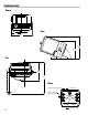
Dimensions Front Side 4.72" 9.9" 10.7" 8.13" 70° Top LectroCount LCR 600 Ø7.
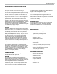
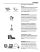
Overview LectroCount LCR 600 Overview General Information The Liquid Controls LectroCount LCR 600 is a microprocessor-based electronic meter register that can be used for Weights & Measures approved custody transfer actions in mobile or fixed installations. The LCR 600 can control a meter system as a stand-alone unit, or it can be used as a slave to a host controller such as a process controller or an in-cab data management system. The LCR 600 is a self-contained unit.
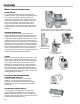
Overview Meter System Components Meter System A Liquid Controls meter system not only accurately measures product, it also regulates and purifies product flow in order to produce the optimal conditions for measurement. Optimal systems typically include an air/ vapor eliminator, strainer, meter, register, and control valve. The LectroCount LCR 600, a register, serves as the central controller of the meter system. Most components in the meter system are hard wired to the LCR 600 via data communication cables.
Overview Meter System Components Epson Slip Printer Epson Roll Printer POD Pulser ∆P Transducer DMS i1000 EZCommand, Cable, and Adapter Printers Printers print delivery tickets to provide a physical record of custody transfers. The Epson slip printer is considered the industry standard for many applications. Multilayered tickets are available to provide a physical record for both customers and business records.
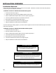
Installation Overview Installation Overview If the LectroCount LCR 600 was ordered as part of a meter system, it will arrive mounted on the meter and prewired to the ETVC probe, air eliminator, and valve. Installation overview for LCR 600 ordered with meter system: 1. Ground truck seat cushion. Page 12 2. Install meter system onto truck or fixed installation. Refer to meter manual. 3. Run the LCR 600’s data and power cable to truck cab or power supply. Page 17 4.
LectroCount Ground Strap Kit LectroCount Ground Strap Kit All seat cushions are grounded in a similar manner. The illustrations on the next page detail the following instructions for grounding three typical types of truck seats. . ESD Precaution . Install the LectroCount Ground Strap Kit before installing the LectroCount register. To ground a truck seat: 1. Identify any adjustable, shock absorbing seat in the truck cab.
Typical Adjustable Truck Seats & Ground Check Typical Adjustable Truck Seats Air Cushion Seat Adjustable for Height (Bostrom 914 Series, National 2000 Series, or equivalent) Air Cushion Seat Adjustable for Height (Dura-Form or equivalent) Bench Seats Adjustable for Distance to the Steering Wheel (Manufacturer Standard or equivalent) Checking for a Good Ground After installing the ground kits, use a multimeter to confirm that the seat and printer are both grounded properly.
LectroCount lCR 600 Mounting Mounting Overview Typically, the LectroCount LCR 600 is mounted directly onto a flow meter; however, some fixed installations require the register be mounted away from the meter. If the meter is equipped with an external POD pulser, the LCR 600 can be mounted up to 1000 wire feet (304 meters) away from the meter (actual distance depends on pulser specifications and wire type).
LectroCount LCR 600 Mounting Mounting Bolt Pattern The LectroCount LCR 600 base casting contains eight bolt holes in an industry standard bolt pattern. The holes are ½" deep and take ¼"-20 screws. If the installation necessitates that you fabricate a bracket, refer to the drawing to the right. LCR 600 Bolt Pattern LC Meters Remove Existing Registration Equipment 1. Depressurize the meter completely. See Warning on pg. 14. 2. Remove the four bolts on the bottom that fasten the register to the meter.
LCR 600 Mounting Neptune Meters Remove Existing Registration Equipment 1. Depressurize the meter completely. See Warning on pg. 10. 2. Remove the mechanical register from the meter. 3. Leave the star-shaped gear and the two square-head studs. 4. Remove the bellows from the front of the meter. 5. Remove the compensator. Neptune Meter Mount the LectroCount LCR 600 1. Install the drive fork and extension piece (pictured below) on the pulser drive shaft located on the bottom of the LCR 600.
Routing LCR 600 Data and Power Cables Data and Power Cable The LCR 600 shipment typically includes a gray 40' power cable and a 40' black data cable prewired to terminal blocks on the LCR 600 CPU board. On typical truck installations, the cables must be routed from the back of the truck, where the LCR 600 is installed, to the front of the truck, where the accessory panel is and the printer is typically installed. The black data cable connects to the printer, typically mounted in the truck cab.
ETVC Installation Electronic Temperature Volume Compensation (ETVC) Installation When ordered as part of a meter system with a LCR 600, the ETVC kit is bolted onto the strainer and wired to the LCR 600 at the factory. ETVC kits can also be ordered and retrofit onto meter systems already in service. Although there are several installation kits—kits are specified according to meter size and application—they are all installed in the same manner.
Valves Single Stage Systems A2847-11 Solenoid-Operated Block Valve Single Stage (S1) Block Valve Liquid Controls’ Valves Overview When ordered as part of a meter system with a LCR 600, Liquid Control’s control valves are bolted onto the meter and wired to the LCR 600 at the factory. Electronic control valves can also be ordered separately and retrofit onto meter systems already in service. These valves will need to be piped and wired in the field. For piping instructions, refer to the valve manual.
Valves Single Stage Valves (cont.) Two Stage Systems A2700 Series Electro-Pnuematic Valve Electro-pnuematic valves use a S1 solenoid-operated valve mounted to a pneumatic actuator to open and close a V-7 valve. These valves are typically used in high viscosity applications like lube oil.
Valves Disconnect Power Disconnect the power before working on the CPU board. Valve Installation If installing the valve yourself, please refer to the valve’s installation and operation manual for mechanical installation. Instructions for wiring Liquid Controls valves to the LCR 600 are on the following two pages. Materials needed for wiring valves: Not supplied with the valve Solenoid 1 Wiring for Single Stage Valves • 20AWG stranded wire (3 per solenoid). Not necessary for 3-Way solenoid valves.
Valves Valve Installation—110VAC Solenoids In order for the LectroCount LCR 600 to control valves with solenoids on 110VAC circuits, you must install a relay switch on the positive leg of the solenoid’s circuit. To wire 110VAC solenoids to the LCR 600: 1. Turn off all 100 VAC circuits before beginning the installation. 2. Install the specified relay switch(es) onto one leg of the 110 solenoid power supply circuit. Relay switch specifications: 3.
Optical Air & Vapor Eliminators Optical Air and Vapor Eliminator Installations Optical Air Eliminator: Refined Fuels Optical Vapor Eliminator: LPG and NH3 When ordered as part of a meter system with a LCR 600, Liquid Control’s optical air and vapor eliminators are bolted onto the strainer and wired to the LCR 600 at the factory. Optical air and vapor eliminators can also be ordered separately and installed onto meter systems already in service.
Pulse Output Device (POD) Pulse Output Device (POD) Installation When ordered as part of a meter system with a LCR 600, Liquid Control’s Pulse Output Device (POD) is installed onto the meter and wired to the LCR 600 at the factory. The POD can also be ordered separately and installed onto meter systems already in service. For mechanical installation instructions, refer to the POD manual. Instructions for wiring the POD to the LCR 600 are provided on this page.
Differential Pressure (∆P) Transducer Differential Pressure (∆P) Transducer Installation When ordered as part of a meter system with a LCR 600, Liquid Control’s ∆P transducer is wired to the LCR 600 at the factory. The ∆P transducer can also be ordered separately and installed onto a meter system already in service. Refer to the ∆P transducer manual for complete installation instructions. Instructions for wiring the ∆P transducer to the LCR 600 are provided on this page.
Remote Display and Auxiliary Outputs To wire an external display to the LCR 600: 1. Attach cable glands and/or conduit connectors to the display and the LCR 600 port(s). 2. Thread the wires through a piece of weatherproof conduit cut-to-length from the display port to a LCR 600 port, pull the wires through the ports, and tighten the connectors. 4. Connect the four display terminals to four terminals on the J18 terminal block of the LCR 600 CPU board.
Printers Printer Installation A Liquid Controls meter system with a LCR 600 typically includes an Epson slip printer or roll printer. Installation is the same for both printers. LCR 600’s are typically shipped with a black-sheathed data cable prewired to terminals J1 and J3 on the LCR 600 CPU board. See instructions on pages 17 for routing the data cable from the back of the truck to the cab. To install the printer: Disconnect Power 1.
Data Communications RS-232 and RS-485 Communications The LCR 600 is capable of interfacing with RS-232 and R-S485 communication protocols. Data connections for these protocols is made at the J2 and J3 terminal blocks. A jumper, located on the left side of the CPU board, can also affect communication protocol; however, it must remain in the B position for all LCR 600 applications. See note and diagram below. Keep the B Position The LCR 600 is shipped with the jumper in the B position. Keep it there.
Power Installation Power Installation Overview When you have made all of the data connections and finished installing the components, connect the power to the LCR 600 and the Epson printer. Before making the power connections, go through the vehicle system checklist below, and ensure that the electrical system of the truck meets the minimum requirements for powering the LCR 600 and the Epson printer.
Power Installation Connect the Power All LCR 600 shipments typically include a 40' gray power cable (100', and 300' are also available) and a 7.5A fuse. Page 17 describes the best practices for routing the gray power cable to the truck cab’s accessory panel. 40’ Gray Power Cable The gray power cable (PN 84046) is prewired to the J8 and J9 terminals on the display CPU board and the J6 terminal on the CPU board at the factory. It includes two 16AWG wires and a ground drain wire. The 7.
Power Installation Epson Printer Power Connections 7.5A In-Line Fuse Chassis or Reliable Ground DC Ground Black Black Data Cable Power Supply Battery or Accessory Panel Red Red Gray Power Cable (see below) LectroCount LCR 600 Power Connections 7.
Post Installation IMPORTANT: Before Sealing the LCR 600 After the LCR 600 is powered correctly, continue on to the LectroCount LCR 600 Setup and Operation manual to setup the LCR 600 for operation. You will want to setup and test the LCR 600 before closing and sealing the unit. Close and Seal the Unit Once the unit has been setup and tested, finish the installation by closing and sealing the housing. The LCR 600 must be environmentally sealed to protect the electronics against the elements.
Post Installation—Bill Of Materials Weights & Measures Seals To detect possible intrusions into Weights & Measures approved calibrations on a LectroCount LCR 600, fillister holes have been drilled into the switchplate screw and the latch. To seal according to Weights & Measures standards, a wire is threaded through the fillister holes and closed with a lead seal.
Bill Of Materials Bill Of Materials—Internal Components 84057 Display Board Cable 81513040 Data Cable 81833 Hollow O-ring Seal MH3 MH5 07677 Ground Screw #8-32 x ¼" MH7 RF1 L10 485-B 485+A J2 PRINTER GND CTS RXD TXD RTS +VP MH4 J3 SERIAL 485 TERMINAL J20 T-CTS 11 12 13 C2 T-RXD +12-24V J1 GND ACC C5+ J6 RS-232 J10 GND GND CTS RXD TXD RTS MH1 C4+ J4 EARTH C3+ P1 24 25 MH1 84050 (84051) Enclosure Base Assy w/ Pulser (w/o Pulser) T-TXD POWER T-RTS J11 MH2 MH4 C1+ C2+
Bill Of Materials 84040-4 (or 84040) CPU Board 81323 J2–2-Pin Connector 81324 J1–5-Pin Connector 485-B 485+A GND CTS RXD TXD RTS +VP 24 25 SERIAL 485 TERMINAL J20 +12-24V PRINTER 81320 J6–3-Pin Connector J3 GND J2 EARTH J1 MH4 11 12 13 GND CTS RXD TXD RTS MH1 81456 J3–6-Pin Connector C2 POWER +5V OUT IN 4 IN 3 IN 1 IN 2 TP1 J6 J7 J10 GND J17 GND A B P1 COUNTER C1 J18 81391 J12–7-Pin Connector OUT5 OUT4 GND OUT3 OUT2 +VP OUT1 PULSE INPUTS J5 J12 AUX OUTPUTS
Liquid Controls 105 Albrecht Drive Lake Bluff, IL 60044 (847) 295-1050 SAMPI Via Amerigo Vespucci 1 55011 Altopascio (Lucca), Italy +39 0583 24751 IDEX Fluid and Metering Pvt. Ltd. Survey No. 256, Alindra Savli GIDC, Manjusar Dist. Vadodara 391 770 Gujarat, India +91 265 2631855 105 Albrecht Drive Lake Bluff, IL 60044-2242 1.800.458.5262 • 847.295.1050 Fax: 847.295.1057 www.lcmeter.