
Setup & Op User guide


27
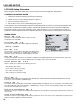
CALIBRATION SETUP
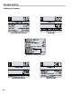
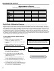
Preparing for Calibration
Before the LCR 600 is put into daily operation, the liquid(s) meant to be measured must be dened and proved. The
Calibration Setup screens provide the means to do so. The LCR 600 can hold a total of 16 different calibrations.
Calibrations must be dened according to type, and they can be named and coded for easy recognition. If the meter
system is equipped with electronic temperature volume compensation, Weights & Measures temperature calibration
can be made on Calibration Setup screen 2. The Calibration Setup screens also provide a eld to set the dwell ow
(S1 Close:) and to calculate a second volume in an additional unit of measurement (Auxiliary Multiplier:
and Auxiliary Unit of Measure:). To prove the meter, you will use one of the BEGIN CALIBRATION
DELIVERY elds and the Pulses/Unit <k-Factor>: eld.
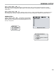
The
Unit of Measurement:
eld is on the
System Setup 1 screen .
CALIBRATION AND PRODUCT TERMINOLOGY
Previous LectroCount models used the terms Product Code, Product Name, and Product Type for calibration purposes.
The LCR 600 has redened these terms for the POS application and replaced them in the calibration setup with Calibration
Code, Calibration Name, and Calibration Type. The denition of “product” has expanded to include not only calibration
characteristics but also pricing and tax information.
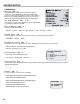
Calibration #
’s can be overwritten and reproved.
Don’t accidentally overwrite a
Calibration #
currently in use.
Be Careful
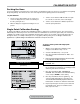
To setup a calibration for a product (before
1. Remove the switchplate and move the selector switch to
the calibration position.
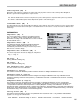
2. Navigate to the Calibration Setup 1 screen.
3. Choose a calibration number (1-16) from the
Calibration #: eld.
4. Dene the calibration #. Enter the Calibration Code,
Calibration Name, and Calibration Type.
5. Navigate to the Calibration Setup 2 screen.
6. If using electronic temperature volume compensation,
enter the correct Compensation Type. The
Compensation Parameter and the Base
Temperature elds will default to the values listed in
the table on page 28. Ensure these values are correct for
your application. Change them when necessary.
7. Make sure the hose is packed. See instructions on page
29.
8. You are now ready to prove the meter system.