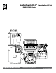
LectroCount LCR-II® Installation & Parts E3650/E3651 Series LectroCount LCR-II Gallons Liquid Controls Group An IDEX Fluid & Metering Business Installation: EM100-10
Table of Contents Introduction Bill of Materials Safety Procedures . .................................................. 2 ESD Protection.......................................................... 4 Dimensions............................................................... 5 Specifications ........................................................... 6 Meter System Overview............................................ 8 LectroCount LCR-II Overview.................................. 10 External Components......
Safety Procedures Safely Evacuate Piping System ! WARNING Before disassembly of any meter or accessory component: ALL INTERNAL PRESSURES MUST BE RELIEVED AND ALL LIQUID DRAINED FROM THE SYSTEM IN ACCORDANCE WITH ALL APPLICABLE PROCEDURES. -Pressure must be 0 (zero) psi. -Close all liquid and vapor lines between the meter and liquid source. For Safety Rules Regarding LPG, refer to NFPA Pamphlet 58 and local authorities.
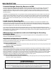
ESD Protection Potential Damages Caused by Exposure to ESD To prevent electrostatic discharge (ESD) damage to LectroCount register electronic components, all LectroCount electronic register truck intallations are required to properly ground truck seat(s) cushions and Epson printers.
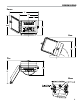
Dimensions Front Side Top Rear 5
Specifications Input/Output Specifications Power Requirements +9 to +28 Volts DC @ less than 3 Amps for entire register including solenoid valves. The system can operate with either a positive or negative ground. Pulse Input +5 to +28 volt peak to peak square wave from an open collector transistor. Quadrature or single channel with a directional logic line. Frequency not to exceed 1500 Hz.
Specifications Weights & Measures - Custody Transfer United States Canada NTEP Certificate of Conformance #86-022. Complies with requirements in NIST handbooks 14 and 44 for use with any approved meter. Measurements Canada Notice of Approval #AV-2342. Complies with Weights & Measures Acts, Regulations, Specifications, Bulletins, and Rulings/Interpretations including specifications SVM-1 and SVM-2 for use with any approved meter.
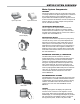
Meter System Overview Meter System Components Meter System A Liquid Controls meter system not only accurately measures product, it also regulates and purifies product flow in order to produce the optimal conditions for measurement. Optimal systems typically include an air/ vapor eliminator, strainer, meter, register, and control valve. The LectroCount LCR-II, a register, serves as the central controller of the meter system.
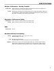
Meter System Overview Meter System Components Epson Slip Printer Epson Roll Printer Remote Display POD Pulser ∆P Transducer DMS i1000 Lap Pad Printers Printers print delivery tickets to provide a physical record of custody transfers. The Epson slip printer is considered the industry standard for many applications. Multilayered tickets are available to provide a physical record for both customers and business records.
LCR-II Overview LectroCount LCR-II Overview General Information The Liquid Controls LectroCount LCR-II is a microprocessor-based electronic meter register that can be used for Weights & Measures approved custody transfer actions in mobile or fixed installations. The LCR-II can control a meter system as a stand-alone unit, or it can be used as a slave to a host contoller such as a process controller or an in-cab data management system.
Installation Overview Installation Overview If the LectroCount LCR-II was ordered as part of a meter system, it will arrive mounted on the meter and prewired to the ETVC probe, air eliminator, and valve. Installation overview for LCR-II ordered with meter system: 1. Ground truck seat cushion. Page 12 2. Install meter system onto truck or fixed installation. Refer to meter manual. 3. Run the LCR-II’s data and power cable to truck cab or power supply. Page 17 4.
LectroCount Ground Strap Kit LectroCount Ground Strap Kit All seat cushions are grounded in a similar manner. The illustrations on the next page detail the following instructions for grounding three typical types of truck seats. . ESD Precaution . Install the LectroCount Ground Strap Kit before installing the LectroCount register. To ground a truck seat: 1. Identify any adjustable, shock absorbing seat in the truck cab.
Typical Adjustable Truck Seats & Ground Check Typical Adjustable Truck Seats Air Cushion Seat Adjustable for Height (Bostrom 914 Series, National 2000 Series, or equivalent) Air Cushion Seat Adjustable for Height (Dura-Form or equivalent) Bench Seats Adjustable for Distance to the Steering Wheel (Manufacturer Standard or equivalent) Checking for a Good Ground After installing the ground kits, use a multimeter to confirm that the seat and printer are both grounded properly.
LCR-II Mounting Mounting Overview Typically, the LectroCount LCR-II is mounted directly onto a flow meter; however, some fixed installations require the register be mounted away from the meter. If the meter is equipped with an external POD pulser, the LCR-II can be mounted up to 1000 wire feet (304 meters) away from the meter (actual distance depends on pulser specifications and wire type).
LCR-II Mounting Mounting Bolt Pattern The LectroCount LCR-II base casting contains eight bolt holes in an industry standard bolt pattern. The holes are ½" deep and take ¼"-20 screws. If the installation necessitates that you fabricate a bracket, refer to the drawing to the right. LCR-II Bolt Pattern LC Meters Remove Existing Registration Equipment 1. Depressurize the meter completely. See Warning on pg. 14. 2. Remove the four bolts on the bottom that fasten the register to the meter. 3.
LCR-II Mounting Neptune Meters Remove Existing Registration Equipment 1. Depressurize the meter completely. See Warning on pg. 14. 2. Remove the mechanical register from the meter. 3. Leave the star-shaped gear and the two square-head studs. 4. Remove the bellows from the front of the meter. 5. Remove the compensator. LectroCount LCR-II Gallons Neptune Meter Place fork and extension on drive shaft Insert cotter pin Mount the LectroCount LCR-II 1.
Routing LCR-II Data and Power Cables Data and Power Cable The LCR-II shipment typically includes a gray 40' power cable and a 40' black data cable prewired to terminal blocks on the LCR-II CPU board. On typical truck installations, the cables must be routed from the back of the truck, where the LCR-II is installed, to the front of the truck, where the accessory panel is and the printer is typically installed. The black data cable connects to the printer, typically mounted in the truck cab.
Electronic Temperature Volume Compensation Electronic Temperature Volume Compensation (ETVC) Installation When ordered as part of a meter system with a LCR-II, the ETVC kit is bolted onto the strainer and wired to the LCR-II at the factory. ETVC kits can also be ordered and retrofit onto meter systems already in service. Although there are several installation kits—kits are specified according to meter size and application—they are all installed in the same manner.
Valves Liquid Controls’ Valves Overview Single Stage Systems S1 Solenoid LectroCount LCR-II When ordered as part of a meter system with a LCR-II, Liquid Control’s control valves are bolted onto the meter and wired to the LCR-II at the factory. Electronic control valves can also be ordered separately and retrofit onto meter systems already in service. These valves will need to be piped and wired in the field. For piping instructions, refer to the valve manual.
Valves Single Stage Valves (cont.) Two Stage Systems A2700 Series Electro-Pnuematic Valve Electro-pnuematic valves use a S1 solenoid-operated valve mounted to a pneumatic actuator to open and close a V-7 valve. These valves are typically used in high viscosity applications like lube oil.
Valves Valve Installation Disconnect Power Disconnect the power before working on the CPU board. If installing the valve yourself, please refer to the valve’s installation and operation manual for mechanical installation. Instructions for wiring Liquid Controls valves to the LCR-II are on the following two pages. Materials needed for wiring valves: Not supplied with the valve Solenoid 1 Wiring for Single Stage Valves • 20 AWG stranded wire (3 per solenoid). Not necessary for 3-Way solenoid valves.
Valves Valves with 110VAC Solenoids In order for the LectroCount LCR-II to control valves with solenoids on 110 VAC circuits, you must install a relay switch on the positive leg of the solenoid’s circuit. Relay switch specifications: Switch: SPST (single pole, single throw) Switch Position: Normally open Contact Rating: Greater than maximum current of solenoid Voltage: +12 VDC To wire 110 VAC solenoids to the LCR-II: 1. Turn off all 100 VAC circuits before beginning the installation. 2.
Optical Air & Vapor Eliminators Optical Air and Vapor Eliminator Installations Optical Air Eliminator: Refined Fuels Optical Vapor Eliminator: LPG and NH3 S3 Solenoid When ordered as part of a meter system with a LCRII, Liquid Control’s optical air and vapor eliminators are bolted onto the strainer and wired to the LCR-II at the factory. Optical air and vapor eliminators can also be ordered separately and installed onto meter systems already in service.
Pulse Output Device (POD) Pulse Output Device (POD) Installation When ordered as part of a meter system with a LCRII, Liquid Control’s Pulse Output Device (POD) is installed onto the meter and wired to the LCR-II at the factory. The POD can also be ordered separately and installed onto meter systems already in service. For mechanical installation instructions, refer to the POD manual. Instructions for wiring the POD to the LCR-II are provided on this page.
Differential Pressure (∆P) Transducer Differential Pressure (∆P) Transducer Installation When ordered as part of a meter system with a LCR-II, Liquid Control’s ∆P transducer is wired to the LCR-II at the factory. The ∆P transducer can also be ordered separately and installed onto a meter system already in service. Refer to the ∆P transducer manual for complete installation instructions. Instructions for wiring the ∆P transducer to the LCR-II are provided on this page.
Remote Display and Auxiliary Outputs Auxiliary Outputs 4 & 5 (LectroCount Remote Display) Auxiliary ouputs 4 & 5 are typically used for the 2¼" E1610 Large Remote Display, but they can also be used with other types of displays. Signals from these outputs duplicate the volume data sent to the LCR-II display. Refer to the LectroCount remote display manual for complete installation instructions. To wire the 2¼" E1610 Large Remote Display to the LCR-II: 1.
Printers Printer Installation A Liquid Controls meter system with a LCR-II typically includes an Epson slip printer or roll printer. Installation is the same for both printers. LCR-II’s are typically shipped with a black-sheathed data cable prewired to terminals J1 and J3 on the LCR-II CPU board. See instructions on pages 17 for routing the data cable from the back of the truck to the cab. To install the printer: Compatible Printers 1.
Power Installation Power Installation Overview When you have made all of the data connections and finished installing all of the components, connect the power to the LCR-II and the Epson printer. But before making the power connections, go through the vehicle system checklist below, and ensure that the electrical system of the truck meets the minimum requirements for powering the LCR-II and the Epson printer.
Power Installation Epson Printer Power Connections LectroCount LCR-II Power Connections Power Check After the LCR-II has been installed, check to make sure that it powers up correctly. The LCR-II display and the printer power light should come on when the truck’s ignition is turned to the ON or to the ACC position. Make sure the printer power switch is on. If the LCR-II or the printer does not power up, check the wiring and the connections on the LCR-II CPU board against the manual.
Post Installation IMPORTANT: Before Sealing the LCR-II After the LCR-II is powered correctly, continue on to the LectroCount LCR-II Setup and Operation manual to setup the LCR-II for operation. You will want to setup and test the LCR-II before closing and sealing the unit. Close and Seal the Unit Once the unit has been setup and tested, finish the installation by closing and sealing the housing. The LCR-II must be environmentally sealed to protect the electronics against the elements.
Post Installation Environmental Sealing Guidelines The LCR-II includes sensitive electronic components, including a micro-controller that can be damaged by the presence of moisture. Therefore, it is essential that all conduit ports, the cover, and the shaft seals be adequately sealed by the installer to ensure watertight integrity.
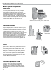
Bill of Materials - External cOMPONENTS 818352 Enclosure Cover Assembly 81915 LCD Display Assembly 07223 Plug ½-40 NPT (7) 06635 Flat Washer .
Bill of Materials - Internal cOMPONENTS PN. 81840: Enclosure, Base Assembly w/o Pulser PN. 81841: Enclosure, Base Assembly w/ Pulser PN. 81512: Cable Assembly Power Input PN. 81330: Cable, Coiled Handset PN. 81513040: Cable Assembly Lap Pad & Printer PN. 81833: Hollow O-Ring Seal PN. 81839: Membrane Switch Harness Assembly PN. 81832: Rotary Switch & Harness Assembly PN. 07677: Ground Screw, #8-32 x 1/4” PN. 81836: Ground Strap (1) w/ Screw & Washer (2) PN. 71319: Desiccant PN.
Bill of Materials - CPU Boards 81920 CPU Board 81324 J1–5-Pin Connector 81323 J2–2-Pin Connector 81456 J3–6-Pin Connector 81320 J6–3-Pin Connector 81392 J8–8-Pin Connector 81391 J12–7-Pin Connector 81837 J15–5-Pin Connector 81322 J14–4-Pin Connector 81321 J13–6-Pin Connector 81547-2 CPU Board 81324 J1–5-Pin Connector 81323 J2–2-Pin Connector 81456 J3–6-Pin Connector 81320 J6–3-Pin Connector 81392 J8–8-Pin Connector 81391 J12–7-Pin Connector 81322 J14–4-Pin Connector 81321 J13–6-Pin Connector
Appendix Wiring Tables This appendix provides a tabular description of the wiring connections made to each LCR-II terminal block. It should be referenced in the event wiring is inadvertently mis-routed in the field, or for general troubleshooting in the event of a problem.
Appendix Wiring Tables This appendix provides a tabular description of the wiring connections made to each LCR-II terminal block. It should be referenced in the event wiring is inadvertently mis-routed in the field, or for general troubleshooting in the event of a problem.
Appendix Setup and Lap Pad Before the LCR-II the register can be setup and calibrated, the initial settings must be entered. To do this, you will need to use a lap pad. The lap pad is connects to a 9-pin female connector on a lap pad adapter. The lap pad adapter connects to the printer and data cable. Instructions for the setup and calibration of the LCR-II are in manual EM100-11, LectroCount LCR-II Setup & Operation.
Appendix Obsolete Products - Hand Held Computer The hand held computer is connected to the LCR-II through the RS-485 port. For this reason, an extra cable must be run from the register (J2) to the Power Supply unit installed in the truck cab. For more detailed information on the setup and operation of the hand held computer, refer to publication number 500096. To connect the LCR-II to the Hand Held Computer: 1.
Liquid Controls 105 Albrecht Drive Lake Bluff, IL 60044 (847) 295-1050 Liquid Controls Europe/SAMPI Via Amerigo Vespucci 1 55011 Altopascio (Lucca), Italy +39 0583 24751 IDEX Fluid and Metering Pvt. Ltd. Survey No. 256, Alindra Savli GIDC, Manjusar Dist.