
Install E3650-E3651 Series Owner manual

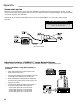

Jumper J10 on LCR-II circuit board must be set for RS-232
communication protocol.
* For a standard RS-232 terminal (other than the Lap Pad), the
red wire is connected to J3-47.
Jumper J10 on LCR circuit board must be set for RS-485
communication protocol.
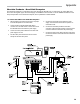
The drain wire must be connected to Pin 13 of terminal J6 in the
LCR-II. It must not be connected in the cab. Trim the drain wire
from the cable end in the cab.
The LCR-II Power cable kit includes a fuse holder and fuse to
protect the system in the event of a short circuit in the cable.
Liquid Controls recommends that this fuse be used in all
installations not having a fused accessory block to protect the truck
in the event of cable faults.
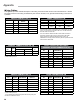
J1-30 GND Black Printer, Pin 7
29 CTS Blue Printer, Pin 20
28 RXD Yellow Printer, Pin 2
27 TXD Orange Printer, Pin 3
26 RTS Brown Printer, Pin 6
J6-13 Earth Drain/Green Wire No Connection
12 GND Black DC Ground
11
+12V In or
+24V In
Red
+12VDC or
+24VDC
J3-51 GND White Ground, Pin 5
50 CTS Green RTS Terminal, Pin 4
49 RXD Gray TXD Terminal, Pin 3
48 TXD Violet TXD Terminal, Pin 2
47 RTS * CTS Terminal, Pin 8
46 +Vo Red Lap Pad +12, Pin 8
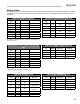
J8-38 GND Black Internal Pulser GND
37 GND Black Push Button GND
36 In 1 Violet INCREASE Button
35 In 2 Gray SELECT Button
34 In 3 Green Int. Pulser “B”
33 In 4 White Int. Pulser “A”
32 +5V Out Red Int. Pulser “+”
31 +Vo
J8-38
37 GND Black Pulser Signal GND
36
35
34 In 3 Green Channel B Output
33 In 4 White Channel A Output
32
31 +Vo Red +V Input
J2-25 485-B Black Violet Terminal
24 485+A Red Red Terminal
36