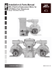
Installation & Parts Manual MA-4 Positive Displacement Meter for LPG Motor Fuel Dispensers (Single & Dual Meter Versions) Installation: M100-11 www.lcmeter.
Table of Contents Description Page Number Safety Precautions .............................................. 2 How LC Meters Work .......................................... 3 Owner’s Information Packet ................................ 4 Installation Requirements .................................... 4-5 Installation ........................................................... 6-9 Mounting Dimensions - Single Meter ...... 6 Mounting Dimensions - Dual Meter ........ 7 Operation Requirements .....................
How LC Meters Work 4. See that the gas is dispersed before resuming business and operating motors. If in doubt, notify your local fire department. department. Stop the leakage only if you can safely reach the equipment. In the event of small, contained fires that you can safely control: Stop the leakage if you can safely reach the equipment. Then use the appropriate extinguisher: Class B fire extinguisher, water, fog, etc., depending on the materials. If in doubt, call your local fire department.
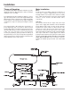
Owner’s Information Packet Serial Number Plate (Side) Is all your documentation included with your meter? LC meters come in many variations. The information sent to you depends on the accessories you have ordered with your meter. Make an inventory of your Owner’s Information Packet. First, find your LC packing slip with the computer printout. Locate the serial number and the meter model number on this printout. Cross-reference the packing slip with the actual meter serial numbers.
Installation & Operation Requirements ! WARNING When a Back Check Valve is used, an automatic safety valve must be installed to prevent pressure build-up in excess of rated working pressure in the meter housing. One automatic safety valve should be installed in each meter. Remove the pipe plug from the front cover or rear cover and insert the appropriate automatic safety valve. • The meter must always be securely bolted to a platform or supporting member, regardless of the mounting position of the meter.
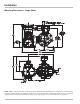
Installation Mounting Dimensions - Single Meter NOTE: Always request up-to-date engineering approved dimensional drawings before starting any construction. Do not rely on catalog pictures or drawings, which are for reference only. After receiving the prints, check to see that all equipment ordered is shown and that any extra pressure taps, plugs, etc. are noted and their size specified.
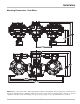
Installation Mounting Dimensions - Dual Meter NOTE: Always request up-to-date engineering approved dimensional drawings before starting any construction. Do not rely on catalog pictures or drawings, which are for reference only. After receiving the prints, check to see that all equipment ordered is shown and that any extra pressure taps, plugs, etc. are noted and their size specified.
Installation Theory of Operation Meter Installation The Liquid Controls MA-4 LPG Meter combines a positive displacement meter, differential valve, strainer, and vapor eliminator in one assembly. Meter: Install the meter assembly in dispenser cabinet to a secure base, using the supplied bracket on the meter housing and the “feet” located on the strainer assembly base. Make inlet and outlet connections at the flanged surfaces on the strainer and differential valve, respectively.
Installation Meter Start-up and Operation Prior to meter start up, use extreme caution. Make sure that: 1. The meter is properly secured 2. All connections are tight 3. All valves are in the closed position Never operate the meter or system when partially filled with liquid, or with pockets of compressed air or vapor present. If these conditions cannot be avoided, air and vapor elimination systems may be required.
Meter Maintenance ! WARNING Relieving Internal Pressure All internal pressure must be relieved to zero pressure before disassembly or inspection of the strainer, air eliminator any valves in the system, the packing gland, and the front or rear covers. Serious injury or death from fire or explosion could result from maintenance of an improperly depressurized and evacuated system. WARNING Procedure for Non-LPG Meters 1. Turn off pump pressure to the system. 2. Close valves before and after the meter. 3.
Meter Maintenance Check the bearing plates. Check the bearing plates for flatness. Use a straight edge. Warped bearing plates can be caused by shock problems that must be resolved. Contact your full-service distributor or the Service Department at Liquid Controls for assistance if this occurs. Examine all fasteners. Make sure fasteners are not bent, rusted, or have pulled threads. The threads should all appear evenly placed. If the bolts are bent, check the housing and cover for flatness.
Pulse Output Device (POD5) The Liquid Controls Pulse Output Device (POD) converts the rotary motion of the Positive Displacement Meter into electronic pulses making it possible to interface the meter to electronic monitoring and control equipment. The POD5 was specifically designed to interface with the MA4 meter and the SCAMP A™ electronics. INSTALLATION: The POD5 comes factory installed on the meter ready for wiring with the conduit orientation in the up position.
Pulse Output Device (POD5) Service Information Due to the simplicity of the POD5, there are few things that can go wrong with the device. However, as with all electronic devices, failures can occur making it necessary to replace failed part(s). There are only three functional spare parts for the POD5; the hub/magnet assemblyNorth Poles, hub/magnet assembly-South Poles, and the encoder assembly.
Pulse Output Device (POD5) Specifications SPECIFICATIONS: Voltage Supply: ..................................... Current Supply: ..................................... Output Signal Resolution: ..................... Square Wave: ....................................... Pulse Timing: ........................................ Rise/Fall Time of Pulse: ........................ Output: .................................................. Operating Temperature: ........................ Humidity Range: ................
Vapor Eliminator & Strainer Maintenance Servicing of the vapor eliminator and strainer involves occasional cleaning of the strainer, or, when required, replacing a float or sticking valve. ! WARNING All internal pressures must be relieved before disassembly or inspection of the strainer, air eliminator, any valves in the system, the packing gland, and the front or rear covers. See “Relieving Internal Pressure” (Page 10). Disassembling and Assembling 1.
Vapor Eliminator & Strainer Maintenance 5. Inspect the vapor eliminator cover O-Ring and ORing groove. The groove in which the O-Ring is located must be free of dirt. The flat face against which the O-Ring seats must be clean and free of nicks and dents that may allow product to leak past the O-Ring seal. Replace the O-Ring seal, if necessary. 6. Remove the four screws on the strainer cover.
Differential Valve Maintenance Faulty operation of the differential valve may be caused by defective valve seals, the spring, or the diaphragm. The diaphragm and the O-Ring valve seat are the only parts that should require replacement in normal service. It is not necessary to remove the valve from the line for disassembly. Disassembling the Valve 1. Remove connecting tube between differential valve and vapor eliminator cover. See illustration on Page 15. 2.
Disassembling the Meter Tools: Rotor Gear Wrench or Socket Bearing Plate Wrench or Socket Counter Bracket Wrench or Socket Drain Plug Allen Wrench Cover Socket or Open End/Box End Spare Displacement Rotor Gear (if unavailable, use a shop rag between gear teeth) Plastic or Rubber Mallet 2 Standard Screwdrivers Emery Cloth, Wire Brush NOTE: See Page 25 for the Torque Chart and the Wrench and Socket Size Chart.
Disassembling the Meter 4. Hold a spare displacement rotor gear between the right displacement rotor gear and the blocking rotor gear to keep them from turning (if unavailable, use a shop rag between gear teeth). Use the rotor gear wrench or socket to remove the right displacement rotor screw and washer. 5. Hold the spare gear between the left displacement rotor gear and blocking rotor gear. Use the rotor gear wrench or socket to remove the screw and the packing gland driver held by the screw. 6.
Removing the Non-Corroded Rotor Gears 7. If the Gears show signs of corrosion, use the alternative method describe on Page 21, “Removing Corroded Rotor Gears”. Insert two standard screwdrivers behind the blocking rotor gear. Gently pry the gear off its rotor tapered end. If the gear does not pry off easily, or feels stuck, use the alternative method described on Page 21, “Removing Corroded Rotor Gears”. 8. Use the same method to remove the left and the right rotor gears.
Removing Corroded Rotor Gears 1. Replace all three rotor gear screws, without washers, halfway onto each of the rotor ends. 2. On the back of the meter housing, remove the screws that hold the rear bearing plate to the housing using the bearing plate wrench or socket. 3. With a plastic or rubber mallet, tap on the heads of the screws lightly and equally. As you tap on the screw heads, the gears are driven off the rotors.
Reassembling the Meter Tools: Cover socket or open end/box end wrench Spare displacement rotor gear Rotor gear wrench or socket Bearing Plate wrench or socket NOTE: See Page 25 for Torque Chart and Wrench and Socket Size Chart. NOTE: The principles of meter disassembly and reassembly are the same for all the Liquid Controls Positive Displacement meters. Although your meter may look slightly different than those pictured, the steps are the same except as noted. 1. Rotor gears are on the front bearing plate.
Reassembling the Meter 4. The rotors should have a small amount of end-play and be easy to turn. Test each rotor one at a time. Turn the rotors to make sure that they revolve freely. Jog the rotors from end to end to check for end-play. If they do not move easily in both tests, remove the rotors and check for burrs and corrosion deposits. Clean them thoroughly. Repeat steps 2,3, & 4. 5. The rotor key is a small wedge of metal. Each rotor has a notch, or “keyway”, to hold a key.
Timing the Rotor Gears Rotor gears are timed by lining up the timing marks (circled in illustration). The blocking rotor gear has a tooth directly in front of its timing mark. On the displacement rotor gears, the timing mark falls in the space between two gear teeth. Make sure that the tooth in front of the timing mark on the blocking rotor gear connects with the space in front of the timing mark on the displacement rotor gear.
Torque Chart Grade 5 Fasteners Inch-Pounds Newton-Meter Bolt Size NOMINAL* NOMINAL* #8 (.164) - 32 UNC-2A 3.5 4.8 #10 (.190) - 24 UNC-2A 5.2 7.1 1/4" (.250) - 20 UNC-2A 7.3 9.9 5/16" (.3125) - 18 UNC-2A 15.3 20.7 27 37 7/16" (.4375) - 14 UNC-2A 43 58 1/2" (.500) - 13 UNC-2A 66 90 5/8" (.625) - 11 UNC-2A 132 179 3/4" (.750) - 10 UNC-2A 233 316 3/8" (.375) - 16 UNC-2A NOTE: Torque tolerance is ±10%.
Troubleshooting ! WARNING All internal pressures must be relieved before disassembly or inspection of the strainer, air eliminator, any valves in the system, the packing gland, and the front or rear covers. See “Relieving Internal Pressure” (Page 10). PROBLEM: Leakage from the cover seal. PROBABLE CAUSE AND SOLUTION: Seal has been damaged due to shock pressure or cover bolts have not been tightened sufficiently. Replace seal and/or re-torque cover bolts.
How to Order Replacement Parts 1. Refer to the exploded view drawings on Pages 2831. Find the four digit item number for the part you want to order. The item numbers are listed on the exploded drawings. The Bills of Material are on the LC public website. Always check the website for the most current BOM. 2. Find the computer printout titled Parts List that has been inserted in the Owner’s Information Packet which was shipped with your order. Look up the item number on the Parts List.
Meter Assembly Exploded View 28
Strainer Assembly Exploded View Single Meter Strainer Assembly A2694 - Temperature Compensated A2696 - Non-Compensated Dual Meter Strainer Assembly A2697 - Temperature Compensated NOTE: • Assembly shown is for systems that use Electronic Temperature Volume Compensation (ETVC). Systems without ETVC use a 1/2" pipe plug (07223) in place of part numbers 81251, 81255, 80584 and 71375. • Probe (71375): Class I Division 1 may require installation with conduit per local codes.
Differential Valve Exploded View 30
Optional Back Check Valve Assembly (PN. 501267) WARNING: When a Back Check Valve is used, an automatic safety valve must be installed to prevent pressure build-up in excess of rated working pressure in the meter housing. One automatic safety valve should be installed in each meter. Remove the pipe plug from the front cover or rear cover and insert the appropriate automatic safety valve.
A Unit of IDEX Corporation 105 Albrecht Drive Lake Bluff, IL 60044-2242 1.800.458.5262 • 847.295.1050 Fax: 847.295.1057 www.lcmeter.com © 2006 Liquid Controls Pub. No.