Installation & Parts Manual MS-Series Spherical Two-Case Meters Installation: M100-20 www.lcmeter.
Table of Contents Description Disassembling the Meter .................................... 21-26 Draining Fluid from the Meter ................ 21 Opening the Weldment Assembly ......... 21-22 Removing Rotor Gears .......................... 22-24 Removing the Bearing Plate & Rotors ... 24-25 Removing Meter Housing Assembly ...... 25 Universal Joint Assembly ...................... 26 Reassembling the Meter .................................... 27-30 Installing the Meter ................................
Safety Precautions NOTICE: This manual provides warnings and procedures that are intended to inform the owner/operator of the hazards present when using the Liquid Controls Meter on LPG and other products. The reading of these warnings and the avoidance of such hazards is strictly in the hands of the owner/operator of the equipment. Neglect of that responsibility is not within the control of the manufacturer of the meter.
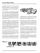
How LC Meters Work Liquid Controls MS-Series meters are positive displacement flowmeters. They are designed for liquid measurement in both custody transfer and process control applications. Because of their simple design, they are easy to maintain, and can easily be adapted to a variety of systems. The meter element (1) is designed with three cylindrical bores (2). A Blocking rotor (3) and two Displacement rotors (4,5) turn in a synchronized relationship within the bores.
Owner’s Information Packet Is all the documentation included with the meter? LC meters come in many variations. The information sent depends on the accessories ordered with the meter. Make an inventory of the “Owner’s Information Packet”. First, find the LC packing slip with the computer printout. Locate the serial number and the meter model number on this printout. Cross-reference the packing slip with the actual meter serial numbers.
Installation Requirements ! WARNING All internal pressures must be relieved before disassembly of the meter, strainer, vapor eliminator, any valves in the system, the pulse output device, or the front and rear covers. LINE PRESSURE MUST BE 0.0 PSI. See “Meter Maintenance” on Page 15 for the procedures to relieve internal pressure. • Make sure that all necessary safety precautions have been taken. Provide for proper ventilation, temperature control, fire prevention, evacuation, and fire management.
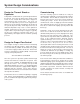
System Design Considerations Flowmeters must be installed properly if accuracy and repeatability of measurements are to be sustained over long periods of time. The system in which the meters are to be used must have provisions for controlling flow, transitional, and no flow conditions. Pressure, both hydrostatic and hydrodynamic, must be an integral part of the variables controlled in the flowing system.
System Design Considerations Design For Calibration Field calibration of meters is essential. Calibration conducted during meter production is to confirm the meter is capable of attaining the required accuracy/linearity and repeatability. Typically, the meter characteristics are: Mechanical Registration • Repeatability: Capable of .02% or better at any flow rate over entire range • Linearity: ± .125% over a 5:1 range • Linearity: ± .22% over a 10:1 range • Linearity: ± .
System Design Considerations Design for Standard Mounting Arrangements (straight through flow) Regardless of meter mounting configuration, accessories such as the air/vapor eliminator must always be mounted in a vertical orientation to permit proper operation of the float-actuated apparatus. Design for Special Mounting Arrangements Special flange arrangements are available as shown. Contact the factory for details or additional information.
System Design Considerations Design for Thermal Shock or Expansion Commissioning Once the metering system is installed, it is ready for commissioning. Filling the system the first time requires care and time. Ensure that the isolation valve on the inlet side of the meter is closed. Pressure the header by starting the pump. At the meter position to be commissioned, “crack” or slightly open the inlet isolation valve until flow into the meter can be heard.
Operation Requirements The meter must remain full of product at all times. An easy way to accomplish this is to put the meter assembly in the line below the piping center-line (a sump position). This requires adding elbows and flanges prior to installing the meter. The meter should be installed with a bypass loop, below the pipe center-line, with block valves upstream and downstream. A block valve should be located in the mainstream, labeled as the bypass valve.
Meter Start Up and Operation Filling the system with a pump: Consult the pump manufacturer for proper pump priming. Once the pump is primed with product, proceed. Prior to meter start up, use extreme caution. Make sure that: 1. The meter is properly secured 2. All connections are tight 3. All valves are in the closed position NOTE: Make sure that your pump can operate against a dead head pressure. If NOT, consult the factory for assistance.
Reversing the Meter Registration The direction of flow is specified by the customer when the meter is ordered. The standard direction of flow is from left to right when facing the front of the meter. A red, pressure sensitive label indicating the inlet is affixed to the meter at the time of shipment. Adjuster drive gear engaged from the top. If the meter is equipped with a strainer and/or valve, the strainer and/or valve MUST be moved when reversing the direction of flow through the meter.
Setting the Standard Adjuster Note: These instructions apply to meters equipped with mechanical output accessories only. If the meter is equipped with an electrical output assembly, refer to the accessory manual, such as the Pulser Manual or LectroCount Manual in your Owner’s Information Packet. 1. See Meter Maintenance on Page 15, and “Servicing the Drive Components” on Page 17, to remove the dust cover. 2. Check meter registration by delivering product to a reliable, accurate prover.
Meter Maintenance ! WARNING RELIEVING INTERNAL PRESSURE All internal pressure must be relieved to zero before disassembly or inspection of the strainers, air eliminators, valves, the pulse output device (POD), or the front and rear covers. Serious injury or death from fire or explosion could result from maintenance of an improperly depressurized and evacuated system. Procedure for Non-LPG Meters 1. Turn off pump pressure. 2. Close valves before and after the meter. 3.
Meter Maintenance Prevent pipe strain or stress from occurring when making meter or accessory repairs. Pipe strain and stress occur when the pipes are not supported or are not aligned correctly to the meter. The weight of the pipes must always be supported independent of the meter. This means that the meter and accessories can easily be removed without affecting the pipes or the pipe alignment. Never leave any of the pipes hanging. Removing flange seals.
Servicing the Drive Components Removing the Dust Cover 1. Cut the dust cover seal wire (if present) with a side cutters. Remove the dust cover screws with a flat blade screwdriver. Remove the dust cover. NOTE: See Relieving Internal Pressure and Weights & Measures in the Meter Maintenance section on Page 15 of this manual. Removing the Adjuster and Adjuster Drive Assembly 2. Record the Adjuster Micrometer setting. 3. Carefully note the adjuster drive gear position.
Servicing the Drive Components Removing the Adjuster and Adjuster Drive Assembly (Continued) 4. Use a flat blade screwdriver to remove the two screws of the upper retaining spring. 5. Use a flat blade screwdriver to remove the two screws of the lower retaining spring. 6. Remove the drive assembly. If there is a need to remove the entire counter adapter assembly, remove the 4 screws located at the bottom end of the assembly.
Servicing the Drive Components Removing the Adjuster and Adjuster Drive Assembly (Continued) 7. Remove the Adjuster assembly by removing the single screw holding it in place. The adjuster can then be rotated clockwise and removed from below. Removing the Packing Gland ! WARNING All internal pressures must be relieved before disassembly of the meter, strainer, vapor eliminator, any valves in the system, the pulse output device, or the front and rear covers. LINE PRESSURE MUST BE 0.0 PSI.
Servicing the Drive Components Standard Packing Gland 1. 2. 3. 4. 5. 6. 7. 8. 9. 10. 11. 12. 13. 14. 15. LPG Packing Gland Housing Drive Blade Bushing Shaft Retaining Clip “U” Cup Rulon Thrust Washer Stainless Steel Thrust Washer Nylon Washer O-Ring Retaining Plate Retaining Plate Screws (2) Roll Pin Output Gear 1:2 Output Gear 1:1 1. 2. 3. 4. 5. 6. 9. 10. 11. 12. 13. 14. 15. 16. The Retaining Plate The retaining plate has four holes” Two that are drilled 1.5” on center Two that are drilled 1.
Disassembling the Meter Standard screwdrivers (2) Spare displacement rotor gear Bearing plate wrench Plastic or rubber mallet Emery cloth Wire brush Tools: Torque Chart Wrench & Socket Size Chart Counter bracket wrench or socket Drain plug wrench Cover socket or open end/box end wrench (See Pages 31 & 32 for the Torque and Wrench & Socket Size Charts) ! WARNING All internal pressures must be relieved before disassembly of the meter, strainer, vapor eliminator, any valves in the system, the pulse output d
Disassembling the Meter 3. When all the screws and bolts have been removed, remove the weldment cover. This exposes the inside of the weldment assembly and provides access to the meter assembly. The meter assembly is held in place by 4 bolts on the inlet side of the meter. This can be either side of the meter depending on the direction of flow. Access to these four bolts is gained by removing the front bearing plate of the meter housing. 4. Remove the O-Ring from the weldment assembly.
Disassembling the Meter 6. Keeping the spare displacement gear between the right rotor gear and blocking gear, use the allen wrench to loosen the screw of the right rotor gear assembly. 7. To loosen the screw of the blocking rotor gear, move the spare displacement rotor gear to between the left rotor gear and the blocking rotor gear to prevent the gears from moving. Once all the screws are loose, remove the screws and washers completely from each of the 3 gear assemblies.
Disassembling the Meter Removing the Rotor Gears 8. Using one or two flat blade screwdrivers, gently pry the gear off its rotor tapered end. Do this for each of the gears. As the rotor gear comes off, remove the key (1) from the rotor keyway (2). Save the key to use when reassembling. Removing the Bearing Plates and Rotors 9. Use the bearing plate wrench or nut driver to remove the screws that hold the front bearing plate to the meter housing. The number of screws varies between the different meter sizes.
Disassembling the Meter 10. When all the bolts are removed, insert a screwdriver into each of the two notches near the dowel pins. Be careful not to mar any of the surfaces. Gently pry the front bearing plate off the dowel pins. Remove the front bearing plate and rotor assemblies by pulling a rotor straight out from the housing. Be careful not to mar any of the surfaces. Removing the Meter Housing Assembly 11. The meter housing assembly is held in place by four bolts.
Disassembling the Meter Universal Joint Assembly 12. The Universal Joint is an extension used to connect the blocking rotor of the meter to the packing gland. When the blocking rotor rotates, the Universal Joint causes the packing gland to rotate which drives the register. This assembly extends through the back of the meter and into the weldment wall through the drive coupling bearing. Universal Joint Components 1. 2. 3. 4. 5. 6.
Reassembling the Meter Tools: NOTE: The principles of meter disassembly and reassembly are the same for all Liquid Controls meters. Although your meter may look slightly different than those pictured, the steps are the same, except as noted. Cover socket or open end/box end wrench Spare displacement rotor gear or shop rag Rotor gear wrench or socket Bearing plate wrench or socket (See Pages 31 & 32 for the Torque and Wrench & Socket Size Charts) Installing the Meter 1.
Reassembling the Meter 3. Install the two displacement rotors. Insert the nontapered ends into the housing. Place each rotor into its respective bore on the bearing plate. 4. Install the bearing plate cover over the three tapered ends and fasten it with the bearing plate screws. Use the bearing plate wrench. The number of screws varies between different meter sizes. 5. Install the rotor keys. The rotor key is a small wedge of metal. Position the keys in each one of the three rotors.
Reassembling the Meter Rotor Gear Timing 6. Slide the blocking rotor gear on its tapered rotor end. Slide the right displacement rotor gear on its tapered rotor end so that the timing marks line up between the two gears. HINT: Before placing the right displacement rotor gear on its end, hold the right rotor gear in position. Turn the blocking rotor gear. Line up the timing marks before placing the right displacement rotor gear on its tapered end. 7.
Reassembling the Meter Reassembling the Weldment Assembly 12. Install a new O-Ring in the groove around the weldment base assembly if required. 13. Position the weldment cover on top of the weldment base so that the cover vent plug is on top. Install the screws around the rim of the weldment cover. Attach the nuts to the back of each screw. Begin by hand-tightening each of the screws. Once this is complete, tighten the nuts and bolts to the proper torque following the tightening sequence on Page 31. 14.
Wrench and Socket Size Chart Bolt Tightening Sequence When placing the weldment cover on the weldment base, it is important that the bolts are tightened in a sequence which reduces the risk of leaking when the system is put back in service. The number of bolts will vary depending on the size of the meter. The general pattern should be followed as pictured. It is important to ensure that the O-Ring does not get pinched during this process. Tighten the bolts following the pattern to 50% of the nominal torque.
Fastener and Torque Chart Meter Model FASTENERS USED Meter Element Weldment Assembly Dust Cover Screws Counter Bracket Screws Bearing Plate Screws Rotor Gear Screws Element Mounting Bolts Drain Plug Cover Vent Plug Weldment Cover MS-7 MSB-7 (6) #10-24 x .38 FLSTR HD SLOT. (4) .312-18x1 HX. HD. SS. (10) .250-20x.75 HX. HD. SS (3) #10-24x.625 HX. HD. SS. (4) .312-18x.75 HX. SCK. HD (1) 1"-11.5 NPT SQ. HD. (2) .500-14 NPT SQ. HD. (12) .500-13x1.75 HX. HD. GR 5 MSA-7 MSAA-7 (6) #10-24 x .
Troubleshooting Identification of Bolt Grades Grade 0, 1, & 2 (No Markings) Grade 6 4 radial dashes, 90º apart Grade 3 2 radial dashes, 180º apart Grade 7 5 radial dashes, 72º apart Grade 5 3 radial dashes, 120º apart Grade 8 6 radial dashes, 60º apart Troubleshooting Problem: Leakage past the packing gland drive shaft housing from internal metering chamber. Probable Cause: Internal seal of the packing gland assembly is worn. Replace packing gland and O-Ring seal.
Troubleshooting Problem: Product flows through the meter but the register does not operate. Probable Cause: 1. Check the packing gland and gear train. 2. If all meter parts are moving, the problem is in the register. Faulty registers should be checked and repaired by a trained technician. 3. Remove the register from the meter. If all meter parts are moving but the output of adjuster assembly is not, adjuster is worn and must be replaced. 4.
How to Order Replacement Parts 1. Refer to the exploded drawings of the meter on Pages 36-39. Find the four digit item number for the part you want to order. 2. Find the computer printout titled Bill of Materials that has been inserted in the red Owner’s Information Packet. Look up the item number on the Bill of Materials. The Bill of Materials shows each item number with a corresponding part number. Find the corresponding part number for the item you want to order.
Illustrated Parts Breakdown Adjuster Housing Assembly NOTE: Numbers shown are ITEM numbers, not Part Numbers. Refer to the Bill of Materials supplied in the red Owner’s Information Packet to locate the PART NUMBER associated with these ITEM NUMBERS.
Illustrated Parts Breakdown Weldment Assembly NOTE: Numbers shown are ITEM numbers, not Part Numbers. Refer to the Bill of Materials supplied in the red Owner’s Information Packet to locate the PART NUMBER associated with these ITEM NUMBERS.
Illustrated Parts Breakdown Meter Element Assembly NOTE: Numbers shown are ITEM numbers, not Part Numbers. Refer to the Bill of Materials supplied in the red Owner’s Information Packet to locate the PART NUMBER associated with these ITEM NUMBERS.
Illustrated Parts Breakdown Complete Assembly NOTE: Numbers shown are ITEM numbers, not Part Numbers. Refer to the Bill of Materials supplied in the red Owner’s Information Packet to locate the PART NUMBER associated with these ITEM NUMBERS.
A Unit of IDEX Corporation 105 Albrecht Drive Lake Bluff, IL 60044-2242 1.800.458.5262 • 847.295.1050 Fax: 847.295.1057 www.lcmeter.com © 2006 Liquid Controls Pub. No.