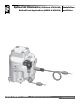
Optical Air Eliminator (US Patent #7000628) Refined Fuels Applications (A8981 & A8981A) Liquid Controls Group An IDEX Fluid & Metering Business Installation and Parts Installation: M300-20
Table of Contents Introduction Maintenance Specifications.................................................. 3 General Information........................................ 3 How Optical Air Eliminators Work................... 4 Disassembly...................................................11 Reassembly.................................................. 13 Troubleshooting............................................ 14 Installation Bill of Materials New Installations........................................
Specifications Optical Air Eliminators (A8981 & A8981A) Environmental Rating NEMA 4X Temperature Rating -40° to 160°F (-40° to 71°C) Safety Designed to meet Class I, Division 2 requirements Products Class 1 Refined Fuels Gasoline, Gasohol, Diesel fuel, and Fuel Oil Class 2 Aviation Av-Gas and Jet Fuel Materials of Construction Class 1 Body: Aluminum Solenoid: Brass Class 2 Body: Anodized Aluminum Solenoid: Stainless Steel Solenoid (S3) Voltage: +12 (± 2)VDC Optional: +24 (± 4)VDC Curr
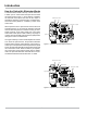
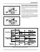
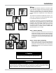
Introduction How the Optical Air Eliminator Works A solenoid valve, located at the top of the air eliminator, is either open or closed. When the liquid level is below the optical sensor (Figure 1), and a delivery is initiated, the solenoid valve opens and vents air and vapor to atmospheric pressure. At the same time, a solenoid-actuated control valve (A2982-11 or A2848-11) closes at the meter outlet.
Introduction How the Optical Air Eliminator Works The figures to the left show a cutaway view of the vent port through the solenoid valve. This port has been designed to optimize the venting of air and vapor from the optical air eliminator. When the liquid level is below the sensor, the S3 solenoid valve is open and allows air and vapor to vent through the solenoid valve as shown in Figure 4.
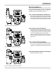
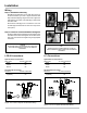
Installation New Installations When ordered with a new meter, the optical air eliminator is supplied mounted atop a strainer on the inlet side of the meter. An example is the meter with high-capacity strainer, two-stage valve, and LectroCount LCR-II® Electronic Register shown in the figure to the right. ½" NPT Port A vent line must be connected from the output port of the optical air eliminator. This connection is ½” NPT.
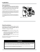
Installation Retrofit Installations These retrofit instructions will show a system using a Hi-Cap strainer/air eliminator; however, the optical air eliminator may also be installed on other LC strainer assemblies used for refined petroleum products. Step 1 - Remove Old Air Eliminator and Baffel Cup After the internal pressure has been relieved from the system and the assembly drained of liquid, remove the four bolts and washers used to fasten the old air eliminator to the top of the strainer.
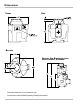
Dimensions Front Side Bottom Optical Air Eliminator with High Capacity Strainer Dimensions shown are not for construction use. Consult factory when certified Engineering Drawings are required.
Installation Wiring The optical air eliminator requires a LectroCount LCR/ LCR-II Electronic Register with CPU board part number 81920 (LC³ with 81924). If the LectroCount does not contain an 81920 CPU board (LC³ with 81924), this board must be ordered as a replacement to the existing CPU board. The 81920 CPU board has an additional connector, connector J15, not present on other board models. On the LC³ 81924 CPU board it is connector J11.
Installation Wiring Step 3 - Reassemble Cable Plug Reinstall the terminal block into the cable plug housing in the same orientation you found it. Tighten the strain relief strap inside the cable plug using the two screws. Tighten the cable gland on the bottom of the cable plug so that it seals around the cable. Reconnect the cable plug to the coil. Place the cover over the cable plug and fasten with the screw to a torque of 8.8 in-lbs (1 Nm).
Maintenance ! WARNING Before disassembly of any meter or accessory component, ALL INTERNAL PRESSURES MUST BE RELIEVED AND ALL LIQUID DRAINED FROM THE SYSTEM IN ACCORDANCE WITH ALL APPLICABLE PROCEDURES. Pressure must be 0 (zero) psi. Close all liquid and vapor lines between the meter and liquid source. Failure to follow this warning could result in property damage, personal injury, or death from fire and/or explosion, or other hazards that may be associated with this type of equipment.
Maintenance Disassembling Step 4 Place the valve body on a flat surface. Using a flat blade screwdriver, remove the two screws which hold the armature guide post and valve body together. Lift the armature guide post off of the valve body. The internal components consist of a plunger and a spring. Inspect the spring for damage. O-rings Step 5 The armature guide post is composed of four components: two O-rings, the guide post, and the flange. Inspect these components for damage.
Maintenance Reassembling Step 1 Place the spring inside the plunger and insert the plunger, spring end first, into the armature guide post. Place the armature guide post assembly on the valve body. Fasten the armature guide post to the valve body using the two screws removed earlier. Two holes of the valve body are threaded and two are not. Make sure the screws are being inserted into the threaded holes. Note that the valve body has a number stamped into it.
Maintenance ! WARNING Before disassembly of any meter or accessory component, ALL INTERNAL PRESSURES MUST BE RELIEVED AND ALL LIQUID DRAINED FROM THE SYSTEM IN ACCORDANCE WITH ALL APPLICABLE PROCEDURES. Pressure must be 0 (zero) psi. Close all liquid and vapor lines between the meter and liquid source. Failure to follow this warning could result in property damage, personal injury, or death from fire and/or explosion, or other hazards that may be associated with this type of equipment.
Bill of Materials - Exploded View Model Number: A8981 & A8981A Italicized part numbers indicate A8981A (Class 2) parts.
Liquid Controls 105 Albrecht Drive Lake Bluff, IL 60044 (847) 295-1050 Liquid Controls Europe/SAMPI Via Amerigo Vespucci 1 55011 Altopascio (Lucca), Italy +39 0583 24751 IDEX Fluid and Metering Pvt. Ltd. Survey No. 256, Alindra Savli GIDC, Manjusar Dist.