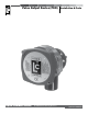
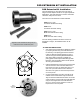
Pulse Output Device (POD) Liquid Controls Group An IDEX Fluid & Metering Business Installation & Parts Operation: EM300-10
Table of Contents Introduction Installation Safety Procedures..................................................... 3 General Information.................................................. 4 POD Models.............................................................. 4 Output Signal Resolutions......................................... 4 Specifications............................................................ 5 Dimensions...............................................................
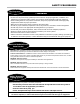
Safety Procedures Be Prepared ! WARNING • Before using this product, read and understand the instructions. • All work must be performed by qualified personnel trained in the proper application, installation, and maintenance of equipment and/or systems in accordance with all applicable codes and ordinances.
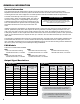
General Information General Information The Liquid Controls Pulse Output Device (POD) converts the rotary motion of the Liquid Controls Positive Displacement Flowmeter into electronic pulses. This allows the meter to interface with a wide variety of electronic monitoring devices and control equipment. The POD operates in standard and bidirectional flow applications. The POD mounts directly to the front cover of any Liquid Controls meter in place of the packing gland.
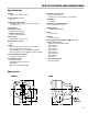
Specifications and Dimensions Specifications Voltage • 9 to 30 VDC; POD5 is 5 VDC Current Supply maximum • 50 mA Output Signal Resolution • 100 pulses per channel per revolution, unscaled See table on page 4 Square Wave Single channel output • Channel A or channel B Quadrature channel output • Channel A and channel B Pulse Timing • Nominal 50% on and 50% off Rise/Fall Time of Pulse • <5 µs Output • Current sinking 100 mA maximum in “ON” state • V+ supply @ 2.2 KΩ in “OFF” state.
Regulatory Compliance Tag Markings EU Explosive Atmospheres symbol DNV 11 ATEX 01600X and IECEx DNV 11.0012X This equipment has been found to comply with the European Directive for Equipment For Potentially Explosive Atmospheres 94/9/ EC (ATEX), and Certification Scheme for Explosive Atmospheres of INTERNATIONAL ELECTROTECHNICAL COMMISSION (IECEx).
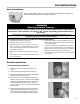
POD Installation New Installations When ordered with the flowmeter, the POD comes factory installed on the meter and ready for wiring. Wiring instructions begins on page 10. ! WARNING Relieving Internal Pressure All internal pressure must be relieved to zero pressure before disassembly or inspection of the strainer, vapor eliminator, any valves in the system, the packing gland, and the front or rear covers.
POD Installation Installing the POD To install the POD onto a flowmeter: POD Extension Kits 1. Verify that the proper POD Model was obtained by comparing the driver tang on the POD to the driver tang on the packing gland that was removed in Step 5 of Removing Existing Hardware on Page 4. There are two types of packing gland/POD driver tangs: blade type and fork type. Blade type packing glands must be replaced with blade type PODs. Fork type packing glands must be replaced with fork type PODs. 2.
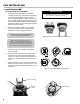
Pod Extension Kit Installation POD Extension Kit Installation The POD Extension is used when the meter has an integral counter adapter bracket or for high temperature applications. The POD Extension is used to extend the connection away from the meter. There are four POD Extension models available.
POD Wiring POD Wiring Wiring Conduit System When wiring the POD, the wires must enter through the POD’s conduit hub. For explosion proof rated systems (Class I, Div 1), the wiring must be in explosion proof rated rigid conduit, or, for high vibration installations, explosion proof rated braided flexible conduit. The conduit must be engaged five (5) full threads into the female hub on the POD to meet explosion proof requirements.
POD Wiring POD Wiring Conversion to Open Drain Output As supplied by the factory, the POD has a 2.2 KΩ pull-up resistor to the positive power supply on each output transistor. The unit can be modified in the field to provide true Open Drain (Open Collector) outputs if desired. To modify the POD to Open Drain outputs: 1. Turn off power to the unit and remove the cover by turning it counterclockwise. 2. Loosen the three circuit board mounting screws using a Philips screwdriver.
POD Wiring Schematics Single Channel Applications For PODs with Serial Number 04-24531 and higher Wiring Guide SP4000, SP3850, IT400 1. Use metallic conduit with individual wires or use 3 conductor, 22 AWG, shielded cable. 2. Strip 1½" off of outer sheathing. Remove exposed shield and drain wire and then tape. 3. Strip ¼" insulation from each conductor and connect to the terminal blocks.
Bill of Materials POD Assemblies Item # Description Part # 4 Screw, #10-24 x .625 09079 5 Screw, #10-24 x .625 40107 8 Set Screw, M4x.
Bill of Materials POD Extension - fork Drive Models 49754 & 49756 Item # Description Part # 1 Pulser Extension Driver N/S* 2 Pulser Housing N/S 3 Screw, #10-24 x 2.
Liquid Controls 105 Albrecht Drive Lake Bluff, IL 60044 (847) 295-1050 Toptech Systems 1124 Florida Central Parkway Longwood, FL 32750 (407) 332-1774 Nateus Business Park Nieuwe Weg 1-Haven 1053 B-2070 Zwijndrecht (Antwerp), Belguim +32 (0)3 250 60 60 SAMPI Via Amerigo Vespucci 1 55011 Altopascio (Lucca), Italy +39 0583 24751 IDEX Fluid and Metering Pvt. Ltd. Survey No. 256, Alindra Savli GIDC, Manjusar Dist. Vadodara 391 770 Gujarat, India +91 265 2631855 105 Albrecht Drive Lake Bluff, IL 60044-2242 1.