INSTALLATION & OPERATION MANUAL Precision Turbine Flowmeters
TABLE OF CONTENTS PAGE # DESCRIPTION 1 Forward 2 Pre-Installation Inspection, Installation 3 Installation (continued) 4 3 Typical Meter Runs 5 Typical Flowstraightener Section 6 FIGURE 1: 1/4” Assembly Procedure 7 FIGURE 2: 1/2” and Larger Assembly Procedure 8 FIGURE 3: MF20-90 Assembly Procedure 9 FIGURE 4: MF100-175 Assembly Procedure 10 FIGURE 5: Corrosive Meter Assembly Procedure 11 FIGURE 6: 3A Sanitary Meter Assembly Procedure
FORWARD Pg.1 A. PRINCIPLE OF OPERATION 1. The precision turbine flowmeter is a volumetric flow measuring device. 2. The flowing fluid engages the vaned rotor causing it to rotate at an angular velocity proportional to the flowrate. 3. The angular velocity of the rotor results in the generation of an electrical signal (AC sine wave type). Summation of the pulsing electrical signal relates directly to the flow rate. 4.
PRE-INSTALLATION INSPECTION Pg.2 Your SPONSLER PRECISION TURBINE FLOWMETER is a measuring instrument capable of providing you with high precision performance over a long period. It should be treated with care and not subjected to rough handling. 1. Unpack carefully and verify the information contained on the packing slip for proper MODEL Number, SERIAL Number, and CALIBRATION Data. 2. Remove the instrument from the plastic packaging and remove the endfitting protectors from the flowmeter housing. 3.
B. PIPING Pg.3 1. General Piping Considerations- As explained in the FORWARD, the fluid moving through the flowmeter engages the angled blades of the turbine rotor. Thus the rotational velocity of the rotor is a function of the fluid velocity and the blade angle engagement. Swirl present in the fluid ahead of the meter can change the effective angle of engagement and, therefore, cause a deviation from the supplied calibration (done under controlled flow conditions).
Pg.4 3 TYPICAL METERING RUNS METERING LOCATION UPSTREAM DOWNSTREAM Pipe fitting immediately preceding metering location Pipe fitting immediately following metering location.
TYPICAL FLOWSTRAIGHTENER SECTION 1/5 DIAMETER Pg.5 2 DIAMETERS Flowstraightener- A full cluster of thin wall tubes fixed within a section of pipe. The length of the internal tubes is equal to 2 diameters of outer pipe. The diameter of internal tubes is equal to approximately 1/5 the inside diameter of outer pipe. This requires 18 to 20 such tubes.
Pg.6 FIGURE 1: 1/4” PRECISION TURBINE FLOWMETER ITEM 1 2 3 4 5 6 7 8 8 DESCRIPTION HOUSING ROTOR BEARING CONE HANGER SHAFT RETAINING RING PICKUP COIL 1 3 4 1 1 2 2 2 1 1 1 4 5 DOWNSTREAM QTY ENDVIEW 5 7 UPSTREAM 6 2 HOUSING: AN, NPT, FLANGED DISASSEMBLY FOR 1/4” METERS 1. Remove retaining ring; Lift out carefully by placing a small flathead screw driver under the radius notch. 2. Remove internals from housing. 3. Review all parts for damage.
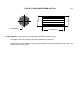
Pg.7 FIGURE 2: 1/2” & LARGER PRECISION TURBINE FLOWMETER ITEM A B C D E F DESCRIPTION BEARING ROTOR CONE CLIP ASSY. LOCK NUT SHAFT QTY 2 1 2 2 2 1 ITEM 1A 1B 1C 2 DESCRIPTION CARBIDE SLV. TEFLON SLV. GRAPHITAR SLV CARBIDE JRNL QTY 1 1 1 1 PICKUP COIL END VIEW B C 2 CARBIDE ONLY HOUSING: AN, NPT, FLANGE (AN shown) 1A FIT TO ROTOR 1B DO NOT REMOVE 1C FIT TO SHAFT DO NOT REMOVE DISASSEMBLY FOR 1/2” AND LARGER METERS FOR SLEEVED BEARING 1. Remove lock nut from shaft end marked “IN”.
Pg.8 FIGURE 3: MF20-90 LO-FLO SERIES FLOWMETER SLEEVED BEARING INTERNALS This assembly references all Model Numbers with Graphitar (GS), Teflon (TS), Carbide (CS), and Fluorosint (FS) sleeved bearing designators DESIGNATOR DESCRIPTION J QTY A B C-2 D-2 E HOUSING SCREW PLUG RETAINER ROTOR/BEARING ASSY.
Pg.9 FIGURE 4: MF100-175 LO-FLO SERIES FLOWMETER G SLEEVED BEARING INTERNALS This assembly references all Model Numbers with Graphitar (GS), Teflon (TS), Carbide (CS) and Fluorosint (FS) sleeved bearing designator. DESIGNATOR DESCRIPTION C-2 QTY A B C-2 D-1 HOUSING SCREW PLUG RETAINER ROTOR/BEARING ASSY.
Pg.10 FIGURE 5: CORROSIVE SERIES FLOWMETER ITEM 1 2 3 4 5 DESCRIPTION END NUT UPSTREAM HANGER ROTOR/PIVOT ASSEMBLY SLEEVE DOWNSTREAM HANGER 1 2 PICKUP COIL QTY 1 1 1 1 1 NOTE: HAND TIGHTEN DO NOT USE FORCE 3 5 4 FLOW DIRECTION OF REASSEMBLY. CORROSIVE SERIES HOUSING DISASSEMBLY FOR CORROSIVE METERS REASSEMBLY FOR CORROSIVE METERS 1. Unscrew end nut from housing. 1. Assemble internals as illustrated. 2. Retract upstream hanger from housing. 2.
FIGURE 6: 3A SANITARY TURBINE FLOWMETER ITEM 1 2 3 4 5 6 DESCRIPTION HOUSING ROTOR CONE HANGER O-RING SHAFT (Carbide or Teflon) Pg.11 QTY 1 1 2 2 1 1 DISASSEMBLY FOR 3A SANITARY METERS REASSEMBLY FOR 3A SANITARY METERS 1. Remove O-ring. 2. Push entire assembly out through the O-ring side of the meter. 1. Assemble the internal assembly as illustrated. 3. Review all parts for damage 2. Push the assembly into the housing on the O-ring side.
© 2009 Pub. No.