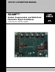
SET-UP & OPERATION MANUAL SCAMP™* Scaled, Compensated, and Multi-Point Flowmeter Signal Conditioner * Protected by U. S. Patent No.
TABLE OF CONTENTS SUBJECT PAGE Table of Contents.............................................................................................................. 2 Overview ........................................................................................................................... 3 Installing SCAMP and Making Basic Electrical Connections ............................................ 4 Powering Up SCAMP...............................................................................................
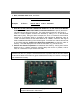
OVERVIEW SCAMPTM is an advanced electronic flowmeter signal conditioner that converts the output signal from the flowmeter to a volumetric unit of measure. SCAMP also temperature corrects the volume delivered to an API standard or to a programmable coefficient of expansion, and has the ability to linearize the flowmeter accuracy at up to sixteen points over its entire flow range.
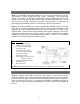
INSTALLING SCAMP AND MAKING BASIC ELECTRICAL CONNECTIONS STEP 1. The SCAMP circuit board measures 4” X 3”. Corner mounting holes (0.144” ID) are provided on 3.640” centers and 2.640” centers, respectively. The circuit board should be mounted in a suitable environmentally sealed compartment, with the top surface of the board (surface with terminal strips and switches) positioned to provide easy access and viewing.
PROGRAMMING METER K-FACTOR Your SCAMP circuit board has been factory calibrated to include a four-digit k-Factor for your specific meter (only if SCAMP is sold separately, i.e., without a meter, is calibration data not entered at the factory). The k-Factor is a number represented by the ratio of pulse edges into SCAMP (from the pulser) and whole pulses per channel out of SCAMP (to the electronic counter). The value of the k-Factor is a number in the range of 4.000 to 9999.
COMPUTING & PROGRAMMING MULTI-POINT CALIBRATION DATA (optional) Multi-point calibration permits compensating for inherent meter error across the full range of flow rates for the meter, thereby providing near-perfect meter accuracy for deliveries from maximum flow to minimum flow. SCAMP allows multi-point calibration for up to 16 different flow rates. Typically, the majority of the selected flow rates will be in the low to mid flow range where most meter inaccuracy occurs.
COMPUTING & PROGRAMMING MULTI-POINT CALIBRATION DATA (Cont.) point, in this case, no left-shifting. The flow rate value must be an integer greater than 3.000. NOTE: If desired, individual calibration points may be disabled by entering any number less than -3.000. ♦ Depress the Data Entry Pushbutton located on SCAMP to enter the new flow rate value into memory. The LED display will now scroll the new value to verify that it has been successfully loaded into memory.
COMPUTING & PROGRAMMING MULTI-POINT CALIBRATION DATA (Cont.) IMPORTANT: The multi-point calibrations computed and entered above are not activated until the “0/1” jumper is moved back to the “0” position and the Function Switch is returned to either the Function 0 (gross measurement mode) or Function 1 through A (net measurement mode). STEP 5C: Entering New Multi-Point Calibration Data (using Prover Method) ♦ Move the Function Switch to the “0” position.
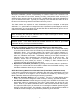
COMPUTING & PROGRAMMING MULTI-POINT CALIBRATION DATA (Cont.) ♦ Next, calculate meter error, as follows. Example: % Error = (Prover volume-Meter volume) x 100 Prover volume % Error = 100.15 -100.17 x 100 = -0.01997% 100.15 ♦ WITH NO FLOW THROUGH THE METER AND STILL IN THE FUNCTION WHERE THE PULSE RATE WAS CAPTURED, set the Data Switches to specify the abovecalculated error at the given flow rate. The value entered must be in the range of 3.000 to +3.000.
TEMPERATURE-VOLUME COMPENSATION (Optional) If temperature-volume compensation is desired, your unit must be outfitted with a standard 100-ohm platinum RTD temperature probe connected as shown in Step 2. Temperature volume compensation permits accurate “net” volumetric deliveries of product taking into account the thermal expansion or contraction of the liquid with changes in temperature. The feature corrects the delivery to a standard reference volume at a liquid temperature of 60oF (15oC).
TEMPERATURE-VOLUME COMPENSATION (Cont.) STEP 8: Temperature Adjustment Your SCAMP unit has been factory calibrated for accurate temperature measurement using a standard 100-ohm platinum RTD with 5 feet of lead wire meeting IEC Class 751-B requirements. If field adjustment is required to match a Weights & Measures thermometer reading, a temperature offset can be entered as follows: ♦ Set the Function Switch to the “C” position. The LED will scroll “A0 Cxx.xx” or “A0 Fxx.
FAULT INDICATOR / ELECTROMECHANICAL TOTALIZER (Optional) Function F (Terminals 9 & 10 or 9 & 6) can be utilized for either of two purposes: 1. To operate a fault indicator such as a LED or relay. 2. To operate an electromechanical or electronic counter as a long-term meter totalizer. IMPORTANT: PERFORM THIS OPERATION BEFORE PROCEEDING! When accessing the electromechanical totalizer k-Factor, ensure that the “0/1” jumper is in the “0” position.
ERROR MESSAGES SCAMP provides error codes that appear on the LED display located on the SCAMP circuit board. Following is a list of all possible error codes along with a description of the error and suggested corrective actions. The errors are classified according to two levels of severity: non-critical errors; and disabling errors. Non-critical errors are not listed in Function Switch position “E”, and will not interrupt operation of SCAMP.
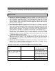
ERROR MESSAGES Disabling Errors Error Code E100 E110 E111 E120 E121 E130 E131 E140 Description The program code space of the SCAMP has been corrupted and needs to be reloaded. Contact Liquid Controls on how to proceed. An excessive number of pulser reversals have occurred. Once flow has stopped, ensure that the pulser is connected properly to the SCAMP and try running flow again. If the problem persists, the pulser may need to be replaced. Scalar adjustment range error.
TROUBLE SHOOTING PROBLEM: SOLUTION: SCAMP will not power up. Using a digital multi-meter, check to ensure that 9-18 VDC is present at the Terminal Strip, Positions 5 and 6. Check further to ensure that the ground lead for the power supply is connected to Terminal 5, and that the positive power supply lead is connected to Terminal 6. Tighten all terminal connection screws. PROBLEM: SOLUTION: Field data is not being stored in SCAMP memory.
APPENDIX A: SPECIFICATIONS SCAMP SPECIFICATIONS Circuit Board Dimensions………………………………………………………4” X 3” Ambient Temperature Range…………………………………………...-30 to +75º C Relative Humidity………………………………………….. 0-100% non-condensing Weatherproof………………………………………………………………………None (Circuit board is designed for installation in customer enclosure) Non-incendiary UL and C-UL……………………Class I, Division 2, Groups C & D Weights & Measures USA………………………………………………………….NIST Handbook 44 Canada (pending)..
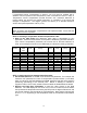
APPENDIX B: SCAMP FUNCTION TABLE “0/1” Jumper Set in Position “0” Function Displayed Value Switch Setting 0 Gross k-Factor (gross metering mode). 1 Linear F compensation parameter and current temperature in degrees Fahrenheit. 2 Linear C compensation parameter and current temperature in degrees Celsius. 3 Table 24 compensation parameter and current temperature in degrees Fahrenheit. 4 Table 54 compensation parameter and current temperature in degrees Celsius.
APPENDIX C: CALCULATING THE K-FACTOR FOR YOUR METER STEP 1: Determine how many whole pulses per unit of measure per output channel are desired for the application. Discussion: If the output counter only counts one channel on one edge (whether rising or falling), then the number desired is usually 1, 10, 100, or 1000 pulses per unit of volume. If, however, the counter uses both channels (e.g.
APPENDIX C: CALCULATING THE K-FACTOR FOR YOUR METER (Cont.) 2. An M5 dispenser meter is to be set to output 250 whole pulses per channel per gallon in order to count into a dispenser head that requires 1000 edges per gallon. Initial k-Factor = 4894.8 edges / gallon (nominal) = 19.5792 250 pulses per gallon Switch setting is dialed to 19582 (1958 with 2 decimal places). Put function switch in function 0 and enter the value by pressing the Data Entry pushbutton. The display will scroll “F19.58“.
SOLD AND SERVICED BY A NETWORK OF HIGHLY TRAINED FULL SERVICE DISTRIBUTORS Backed By Our Worldwide Reputation For Quality, Accuracy and Advanced Design. Warranty: Liquid Controls (“Seller”) products are warranted against defects in materials or workmanship for a period of one (1) year from date of installation, provided that the warranty shall not extend beyond twenty-four (24) months from the date of original shipment from seller.