TABLE OF CONTENTS APPLICATION ............................................................................................................................................. 1 FEATURES .................................................................................................................................................. 1 DESCRIPTION ............................................................................................................................................. 1 WORKSHEET .............
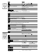
APPLICATION FEATURES * Pulse or Analog Input (with Totalizing Integration) * Display Total, Rate or Grand Total * 2 Presets - User Selectable for Total, Rate or Grand Total * Pulse Input to 20 KHz Count Frequency * 16 Point Linearization * K - Factor Programmable to 8 Places * Security Lockout * 2 way RS232/422/422M Communications * NEMA 4X Front Panel * Scaleable 4 - 20mA Output of Rate * Scaled Pulse Out, Frequency Selectable Batch control, cut to length, packaging, blending.
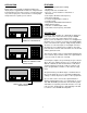
PRE A PRE B A B 1 2 3 4 5 6 7 8 9 ENT 0 CLR RATE/TOTAL MENU C D WORKSHEET MODEL # SERIAL # UNIT # COUNTER LOCKOUT CODE __ __ __ __ K-FACTOR __ __ __ __ __ __ __ __ PR-LCK PR-UNLK Reset to 0 Set to Preset PRESET A __ __ __ __ __ __ __ __ DECimal LOCation (0-8) 8 7 6 5 4 3 PRESET B __ __ __ __ __ __ __ __ 2 1 0 none RELAY Open Collector RATEMETER A TOTAL K-FACTOR __ __ __ __ __ __ __ __ A GRand TOTal WINDOW (02-24) __ __ A RATE DURation of A (0.0-9.9) __ .
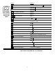
SETUP PROCEDURE NOTE: Start here and finish to the end. If you make a mistake, press ENT until you reach the beginning.
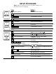
PRESS STEP 4 SETTING THE RATEMETER DISPLAY D MENU FLASHES TO DEV TYP ENT RT B (SET UP RATEMETER) CNT (RATE OR COUNT) K FACTOR FLASHES; THEN SHOWS CURRENT K-FACTOR CLR 0 FLASHES D 8 7 1 7 . 8 FLASHES (PRESS D FOR DECIMAL POINT) K FACTOR IS DIVIDER. IT CONVERTS INPUT TO ENGINEERING UNITS.
PRESS STEP 6 SETTING THE COM. OUT CARD DISPLAY D MENU FLASHES TO DEV TYP D LOCKOUT D OUTCARD ENT (OUTCARD SELECTED) UNIT ## CLR SKIP IF NOT USED 1 ENT UNIT 00 2 (AS AN EXAMPLE) UNIT 12 (UNIT LABELED 12) PL SER * ENT BAUDRATE FLASHES THEN LAST BAUDRATE USED.
PRESS STEP 7 SETTING RATE OR COUNT FOR ANALOG OUTPUT SKIP IF NOT USED DISPLAY D MENU FLASHES TO DEV TYP D LOCKOUT D OUTCARD D ALG OUT ENT (ANALOG SETUP SELECTED) ANLG RT (4-20mA OUTPUT FOR RATE) D (PRESS D TO TOGGLE BETWEEN SELECTIONS) ANLG CT (4-20mA OUTPUT FOR COUNT) ENT (ANLG RT OR ANLG CT SELECTED) SET LOW FLASHES THEN CURRENT LOW SETTING CLR 0 FLASHES 1 2 5 5 D 1 2 5 . 5 FLASHES (PRESS D FOR DECIMAL POINT) AS AN EXAMPLE (IN THIS CASE 125.5 = 4mA) ENT (LOW SET AT 125.
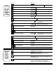
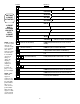
PRESS STEP 9 SETTING RELAY FUNCTION AND ON TIMES DISPLAY D MENU FLASHES TO DEV TYP D LOCKOUT D OUTCARD D ALG OUT D OUT FREQ D RELAY ENT (RELAY SELECTED) A GR TOTAL (RELAY A SET TO GRAND TOTAL) D A RATE (IF RATE SELECTED, DURATION IS DISABLED) D A TOTAL (RELAY A SET TO TOTAL) ENT (PRESS AS DESIRED) DUR A #.# CLR 1 DUR A 0.0 2 (AS AN EXAMPLE) DUR A 1.2 (RELAY ACTIVATES FOR 1.2 SEC.
PRESS SETTING 16 POINT K-FACTOR 16 POINT ONLY APPEARS ON UNITS WITH 16 POINT OPTION NOTE: If TEST is entered, point data can be entered exactly as in selected time entries. However, when the unit "runs" in Test Mode "K-factor is always 1. "Rate" (R) displays frequency (inputs per second). Counter displays 1 count per each input. NOTE: "BAD SEQ" will appear if frquencies are not in ascending order with point numbers.
SPECIFICATIONS Control Outputs (Each of two outputs) 1) NPN Transistor Version: (Optional) Open collector sinks max. 250mA from 30 VDC when active. (When relay is used, 10 VDC is provided at transistor outputs through relay coil. If greater than 2mA is used, relay will remain energized. Applying greater than 10 VDC may destroy unit. Transistor will sink 100mA in “ON” state). 2.) SPDT Relay Version: 10A 120/240 VAC or 28 VDC (Standard) Display 8 Digit, .55” Segment, Red Orange, LED.
Press the “C” button while the units is displaying the batch to display the rate; “R” is displayed on the left side of the display. OPERATIONS Presets Two control presets are provided on the unit. The preset numbers can be made to flash without interrupting the control function by pressing “A” (Preset A) or “B” (Preset B). Press “ENT” to return to rate or total display. Change the preset by clearing the flashing preset number and keying in a new number before pressing the “ENT” button.
APPLICATION PULSE INPUTS The unit accepts output pulses from most encoders, prox. switches or contactors. Connect the pulse to Input A Pin 4. The unit counts on the negative edge of a pulse: Low: 0 to 1 VDC, High: 3 to 30 VDC. SOURCING INPUT - Has a 10K Ohm pull down resistor to ground and must be driven high by a sourcing device such as a PNP transistor or a contact to +DC, Pin 13. SINKING INPUT- Has a 4.
4-20mA Square Law Table mA Input Pulse/Sec mA Input Pulse/Sec 4 0000 10 6123 5 2500 12 7071 6 3535 16 8660 7 4330 18 9354 8 5000 20 10000 Recalibration should only be attempted by someone who has the equipment to generate a very accurate low and high signal and who has the training to open the unit and work with grounded equipment necessary to protect the static sensitive CMOS circuitry. Set the ratemeter as follows: K Factor = 1, sig. fig. = 6, window = 02 and the weight = 0.
the unit is displaying the batch. “R” is displayed on the left side of the display to indicate that rate is being displayed. The unit calculates the rate from the period between pulses. The unit measures the average time between pulses, divides this by the K - Factor and a reciprocal math calculation to find the rate per second. As long as pulses come in faster than 3 per second the unit will update each second.
ASCII characters and parity with two additional bits of “Start” and “Stop” to make up the standard ten bit character. (See Unit setup to select and enter desired Code Number, Baud Rate and Parity). RS422M has automatic baud rate selection and uses an eight bit word, up to 256 units can be linked together. LOCKOUT Unauthorized front panel changes can be prevented by entering a four digit code chosen by the user in the LOCKOUT setup mode. The unit leaves the factory with code 1,000.
RS422 ELECTRICAL REQUIREMENTS SERIAL INTERFACE OPERATION The input of the unit follows the standard E1A high impedance minimum of 12K Ohms. When the 422 + (A) input is more positive than the 422 - (B) input by .2V to 6V, a “1” or “Mark” condition is recognized. When the 422+ input .2V to 6V, a “0” or “Space” is recognized. Data is recognized by the popularity of the voltage difference between the two lines.
Following are two examples of requests and responses.
RS422 WIRING The unit RS422 option has a subminiature D 37 pin female connector and is wired as a DCE (Data Communication Equipment) device. It is designed to be connected to a DTE (Data Terminal Equipment) device. If it must be connected to a DCE device, it will be necessary to cross wires 4 and 6 as well as 22 and 24 at one end of the connector harness.
A) Set the 16 point units to “TEST” and ENT point 00 to go to the run mode. B) At the lowest desired flow rate, rest the counter and let the unit count the incoming signal while the rate displayed is recorded. C) Interrupt the input signal when the known tested volume has gone through the flow meter. Switch to count display and read the number of counts that came in from the known volume as displayed on the unit.
COMMUNICATION FOR 16 POINT When 16-Point option is supplied with either RS232 or RS422 option, data can be read and changed as explained under Communication Section of the manual. IRREGULAR SHAPE VESSEL APPLICATION NOTE; MEASURE VOLUME IN IRREGULAR SHAPED VESSELS WITH 16-POINT LINEARIZATION OPTION. In the past it was difficult to calculate the volume of liquid and set up the equation or computer model to display the volume in containers with odd shapes.
20