INSTALLATION & INSTRUCTION MANUAL SP3000 FLOW COMPUTER DOC#: MN-3000.
- WARNING This instrument contains electronic components that are susceptible to damage by static electricity. Please observe the following handling procedures during the removal, installation, or handling of the internal circuit boards or devices. HANDLING PROCEDURES 1. Power to unit must be removed. 2. Personnel must be grounded, via wrist strap or other safe, suitable means, before any printed circuit board or other internal device is installed, removed, or adjusted. 3.
TABLE OF CONTENTS INTRODUCTION 4 1.1 1.2 1.3 1.4 1.5 GENERAL DESCRIPTION FEATURES APPLICATION GENERAL SPECIFICATIONS INPUT SPECIFICATIONS 1.51 ANALOG INPUTS 1.52 RTD TEMPERATURE INPUTS 1.53 DIGITAL FLOW INPUT 1.6 OUTPUT SPECIFICATIONS 1.61 ANALOG OUTPUT 1.62 DIGITAL FLOW PULSE OUTPUT 1.63 RELAY OUTPUTS 1.64 AUXILIARY POWER OUTPUT 1.7 RS-232 COMMUNICATIONS PORT 1.8 DATA DISPLAY AND KEYPAD 4 4 5 6 6 6 7 7 8 8 8 9 9 9 10 INSTALLATION 10 2.1 MOUNTING THE INSTRUMENT 2.
MODEL SP3000 MASS FLOW COMPUTER INTRODUCTION 1.1 GENERAL DESCRIPTION The Model SP3000 is a microprocessor based instrument designed to measure and compensate flow in an industrial environment. Three inputs - temperature, pressure, and flow – are provided for calculating the flow at standard conditions. Special signal conditioning circuitry is included to allow direct connection of 2, 3, or 4 wire platinum Resistance Temperature Detectors (RTDs), voltage inputs or current loops.
1.
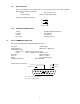
1.4 GENERAL SPECIFICATIONS Operating Temperature: Storage Temperature: Humidity: Front Bezel: Case: Dimensions: Voltage: Power Consumption: 1.5 o o o o 32 to 122 F (0 to 50 C) o o o o -10 to 160 F (-32 to 71 C) 0 to 90% Non-Condensing NEMA 4X ABS Plastic See page 2-1, fig 2-1 115 or 230 VAC +/- 15% (Switch Selectable) 50/60 Hz, 24 VDC +/- 20% 10 Watts max. INPUT SPECIFICATIONS The following applies to all inputs in all modes. Inputs are referenced to the signal ground.
1.52 RTD TEMPERATURE INPUTS Compatible RTD type: (a=0.00385; DIN 43-760 Calibration) Configuration: Excitation Current: Max Fault Current: Max Voltage on Sense Inputs: Rejection of 50-60Hz signal: (Automatically based on line frequency) Raw Accuracy: Temperature Range: 100 ohms Platinum 2, 3, or 4 wire 2mA typical 15mA 50 VDC 40 dB (minimum) 0.2% FS RTI o o -323.5 to +1378.7 F o o (-197.5 to +748.1 C) Typical RTD Schematic: 1 2.2 VDC @ 2mA 20K 2 1.5 F 1.5 F A/D ~ 20K 3 100K 4 1.
1.6 OUTPUT SPECIFICATIONS 1.61 ANALOG OUTPUT Number: Range: Compliance Voltage Range: Load Type: Accuracy: Update Rate: 1 4-20mA DC, sink only 3.0-24 VDC Non-Inductive +/- 100 µA 1 Hz Analog Output Schematic: 19 CPU A/D ~ 100 18 1.62 DIGITAL FLOW PULSE OUTPUT This output is intended to drive a counter with a minimum input impedance of 1000 ohms. It is also compatible with TTL, LSTTL, and 5V CMOS logic inputs. It is slew rate limited to help prevent RFI. Number: Output High Voltage No Load: 4.
1.63 RELAY OUTPUTS One relay is provided as a flow alarm and a second is provided for the other alarm conditions. Each has the following specifications: Type: Dry contact, Form C Contact Rating: 10A at 115/230 VAC/28 VDC Typical Relay Output Schematics: 22 23 24 1.64 AUXILIARY POWER OUTPUT Voltage: Isolation: Current: Protection: 1.
1.8 DATA DISPLAY AND KEYPAD Internal 2 line by 20 character dot matrix LCD display. Sealed, 16 key panel featuring numeric keys 0-9, plus the following keys: A B C D ENT CLR Advance through menus Back up through menus Cancel current menu selection Decimal point key General purpose enter or recall data key Data clear key INSTALLATION 2.1 MOUNTING THE INSTRUMENT The Model SP3000 can be mounted in a user panel greater than 0.047” (1.2mm) and less than 0.187” (4.7mm) thick.
2.2 CONNECTING INPUTS AND OUTPUTS Make sure all power is disconnected before making any electrical connections. All connections are completed at the rear terminal strips as indicated in the external wiring diagram. If cables are in areas with heavy electrical fields, shielding will be required for noise immunity. One end of the shielding should be connected to earth ground.
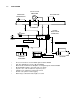
POWER SP714 REV B TEST OUTPUT SIGNAL SENS (JU1 INSTALLED) S1 2 3 4 5 PULSE INPUT GROUND (SHIELD) 30 31 32 1 FLOW COMPUTER D2 17 18 R1 D1 + 24 V J1 B SIG IN - A SIG IN + - DC (GND) SIGNAL OUT + 24 V RETURN CHASSIS GROUND +24 VDC PULSE INPUT CONNECTION PICKUP COIL SP717 REV A D1 OUTPUT SIGNAL (JU1 INSTALLED) 3 4 5 PULSE INPUT GROUND (SHIELD) 30 31 32 2 17 18 1 FLOW COMPUTER D2 + 24 V J1 B SIG IN - A SIG IN + - DC (GND) SIGNAL OUT + 24 V RETURN CHASSIS GROUND +24 VDC PULS
1 2 3 4 5 RTD SENSE + 1 RTD EXCITATION + 2 3 4 5 RTD SENSE + 1 RTD EXCITATION + 2 3 4 5 RTD SENSE + RTD SENSE RTD EXCITATION GROUND (SHIELD) 2 WIRE CONNECTION RTD SENSE RTD EXCITATION GROUND (SHIELD) 3 WIRE CONNECTION RTD SENSE RTD EXCITATION GROUND (SHIELD) 4 WIRE CONNECTION RTD WIRING DIAGRAMS FLOW COMPUTER 4-20mA T/C TRANSMITTER 4 5 6 I IN + 30 31 32 + 24 V GROUND (SHIELD) V IN + 24 V RETURN CHASSIS GROUND TEMPERATURE TRANSMITTER 4-20mA CONNECTION Figure 2-4 Temperature Transmitt
FLOW COMPUTER 4-20Ma PRESSURE TRANSMITTER + I IN + 30 31 32 - 10 11 12 - + 24 V GROUND (SHIELD) V IN + 24 V RETURN CHASSIS GROUND 4-20mA CONNECTION FLOW COMPUTER 5 VOLT PRESSURE TRANSMITTER 10 11 12 I IN + 30 31 32 + 24 V GROUND (SHIELD) V IN + 24 V RETURN CHASSIS GROUND 0-5 VOLT CONNECTION Figure 2-5 Pressure Transmitter Analog Input Wiring Diagrams 14
FLOW COMPUTER STRIP CHART RECORDER 19 20 21 30 31 32 - SINK (4-20mA) + 24 V PULSE OUT GROUND (SHIELD) + 24 V RETURN CHASSIS GROUND ANALOG OUTPUT CONNECTION Figure 2-6 Analog Output Wiring Diagram FLOW COMPUTER REMOTE ELECTRONIC COUNTER 19 20 21 + 12345678 - SINK (4-20mA) PULSE OUT CHASSIS GROUND PULSE OUTPUT CONNECTION Figure 2-7 Pulse Output Wiring Diagram 15
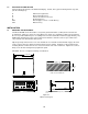
Figure 2-8: Wiring Diagram-2-wire Probe 16
Figure 2-8: Wiring Diagram-2-wire Probe 17
PROGRAMMING CONSIDERATIONS Programming the SP3000 Flow Computer for the desired operation is very simple. All programming selections and data entry are accomplished via the 16 keys located and labeled on the front panel. The software in the unit contains two Top Level Menus: “Setup” Menu and “Running” Menu. The “Setup” Menu allows the selection of operating parameters and entry of data variables. The “Computation” selection sets the formulas used to process the raw input data into meaningful information.
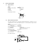
3.1 FRONT PANEL KEYPAD OPERATION Programming is accomplished via the 16 keys labeled and located on the front panel. SPONSLER CO., INC. SP3000 Sponsler V6.13 MS197 Run? ADVANCE A BACKUP B CANCEL DEC PT C D 1 2 3 4 3 6 7 8 9 ENT 0 CLR The function of each key is described below: ADVANCE A Advances to the next item in the menu or sub-menu. If the last item in the menu is displayed, pressing this button will have no effect on the display.
DISPLAY SHOWS PRESS Operating Data Scroll A Running... Show Data? A Running... Go to Standby? ENT Sponsler V6.13 MS197 Run? (This display indicates that the unit is in the “Setup” mode. If the unit was in the “Setup” mode when the power was removed, the unit will return to this display on power up) The function keys allow entry to the menus and sub-menus for selecting operating options or entering numerical parameters. 3.
Liquids – Mass: uses volume and temperature to yield a compensated Mass flow rate displayed in lbm/min (kg/h) and total in lbm (kg). Liquids – Volume: uses volume and temperature to yield a compensated Mass flow rate displayed in GPM (1/s) and total in gallons (liters). uses volume, pressure and temperature to yield a compensated Mass flow rate displayed in lbm/h (kg/h) and total in lbm (kg) as well as Heat flow rate displayed in Btu/h (kW, kcal/h, MJ/h) and total in kBtu (kWh, Mcal, MJ).
3.3 SELECTING THE ENGINEERING UNITS Engineering units establish the measuring system that is used for entry and display of the operating parameters.
Input Configuration: Pressure? A To advance Input Configuration Menu ENT To access Pressure Input Type Menu Flowchart Representation of Hardware Menu: Sponsler V6.
3.5 SETTING THE VARIABLES The variables determine how the input signals are interpreted by the software to display and output the compensated flow. The parameters required for proper calculation are determined by the Computation, Engineering Units, and Hardware Selections. The unit will automatically prompt for the required parameters. Use the numeric keypad to input the required variables. The D key sets the decimal point when entering a numerical value.
Press alarm set point Lo alarm? -- Enter Low Pressure value at which the unit activates an alarm relay (i.e. 5PSIG. Enter 5. Alarm relay is activated when pressure input indicates 5 PSIG) Press alarm set point Hi alarm? -- Enter High Pressure value at which the unit activates an alarm relay (i.e. 500 PSIG. Enter 500. Alarm relay is activated when pressure input indicates 500 PSIG) SPECIAL NOTE: To set the flow computer to follow the saturated steam curve with 1.
Notes: 1. These prompts do not appear if Hardware is RTD (100 ohms). The resistance input is referenced to a look-up table to determine the temperature. 2. This prompt appears if a liquid computation is selected (Liquid-Mass, Liquid-Volume, HeatLiquid, Del Heat-Liquids). 3.53 SETTING THE FLOW VARIABLES The Flow variables determine how the input signals from channel 3 are interpreted.
NOTES: 1. Used in Ideal Gas equation only. 2. Not used in Idea Gas-Volume or Steam equations. 3. Used in Liquids equations only. 4. Used in Heat-Gas, Del-Heat-Liquids and Heat-Mass equations only. 3.55 FLOWCHART: DIGITAL PULSE- SIXTEEN POINT Select input item: Flow input? ENT Linearize 16 Point? ENT Enter Point Freq. 01? ** Refer to section 3.551 & 3.
3.551 DIGITAL PULSE – SIXTEEN POINT PROGRAMMING The 16 Point Linearization is used when the flowmeter gives a non-linear signal. The unit uses up to 16 different frequency and K-Factor entries to form a curve for linearizing the input signal. SPONSLER, INC. STRONGLY RECOMMENDS THOROUGH REVIEW AND UNDERSTANDING OF THIS SECTION PRIOR TO PROGRAMMING THE 16 POINT MENU. NOTES: 1 A minimum of three points must be set up. 2.
3.552 PROGRAMMING EXAMPLE: `Flowchart: Digital Pulse – Sixteen Point **NOTE: This is an example of 16 point programming using calibration data for turbine Serial No. 107221. (See next page) Actual Calibration data must be entered for the specific turbine flowmeter used with the unit. Select Setup item: Flow input? ENT Linearize 16 point? ENT Enter point Freq 09? Press 834 Press ENT Freq 09? 834.0000 K-Factor 09? Press 2274834 Press ENT Enter point Freq 01? Press 0 Press Freq 01? 0.
SPONSLER CO., INC. WORK ORDER #: 9334 2363 SANDIFER BLVD. WESTMINSTER S.C. 29693 USA CALIBRATION #: 1 SERIAL NO.: 107211 FLUID: AIR HOUSING MATERIAL: 304 TEST STAND NO.: 2 ROTOR MATERIAL: 17-4 CALIBRATED BY: HR BEARINGS: CRYO COIL NO.:RF22M 1ea. DATE: 13-Jan-92 MODEL NO.: MF40-CB-PH-1/4A-4RFX TEMP. TRUE VOL. RATE TIME TOTAL APPROX. DEG.FAR. ACFM ACFM SECONDS CYCLES FREQ. CPS 0.004822 0.0531 5.447 11955 2195 2479318.1 0.0507 5.710 11917 2087 2471437.4 3 0.0480 6.
3.6 ANALOG LINEAR INPUT SETTINGS Graphical representation of the Analog Linear sub-menu Select Setup item: Flow input? ENT NOTES 1 Gas compressibility Z Factor? Enter the compressibility factor of the gas being measured Specific gravity Gravity? Enter the specific gravity constant calculated at standard or the Base Reference Temperature for the product being measured At input = minimum Lo flow? Enter the flow value at which the analog input is lowest (i.e. no flow = 4.00mA.
3.61 ANALOG 16 POINT INPUT SETTINGS Select Setup item: Flow input? ENT Linearize 16 Point? NOTES 1 ENT Enter Point Actual 01? ENT Actual 01? 0.000 K-Factor 01? Gas compressibility Z Factor? Enter the compressibility factor of the gas being measured Specific gravity Gravity? Enter the specific gravity constant calculated at standard or the Base Reference Temperature for the product being measured At input = minimum Lo flow? Enter the flow value at which the analog input is lowest (i.e.
3.7 ANALOG ORIFICE/PITOT INPUT SETTINGS Graphical representation of the Analog Orifice/Pitot sub-menu Select Setup item: Flow input? ENT NOTES 1 2 Gas compressibility Z Factor? Specific gravity Gravity? Meter compensation Factor (K1)? At input = minimum Delta P lo? At input = maximum Delta P hi? Low Flow Cutoff? 3 Thermal Expansion C(X10E-6)? 4 Mean Spec Heat? Flow alarm set point Lo alarm? Flow alarm set point Hi alarm? NOTES: 1. Used in Ideal Gas equations only. 2.
3.8 SETTING THE FLOW OUTPUT VARIABLES The Flow Output Variables determine how the output signals reflect the compensated flow. The Flow Output sub-menu is the same for all Computation or Hardware Selections. NOTE: It is not necessary to set up the Flow Output if it is not required.
Sponsler V6.13 MS197 Clear Totalizer? ENT Totalizer Cleared This message is momentarily displayed to verify that the totalizer is cleared. The menu then advances to the next item Sponsler V6.13 MS197 Check Alarm? * To Clear Totalizer in “Running” Menu: Press A Running... Show Data? A Running... Go To Standby? A Running... Setup Display? A Running... Setup Print List? A Running... Print System Setup? A Running...
CHECKING THE ALARM: VIEW THE MOST RECENT ALARM CONDITION If the alarm should go off, the point which went into alarm most recently may be checked and quieted from either of the Top-Level menus. To Check the Alarm in “Setup” Menu: Sponsler V6.13 MS197 Run? A Sponsler V6.13 MS197 Set Computations? A Sponsler V6.13 MS197 Engineering Units? A Sponsler V6.13 MS197 Set Hardware? A Sponsler V6.13 MS197 Set Variables? A Sponsler V6.13 MS197 Clear Totalizer? A Sponsler V6.
LOCK/UNLOCK Lock is used to prevent unwanted changes to programming. No changes through the front panel or RS232 port can be made while the unit is locked. The lock may be initialized in either the “Setup” or “Running” mode. Once the unit is locked, the operating mode can’t be changed. If unit is locked in “Setup” mode, “Running” mode can’t be accessed. If the unit is locked in “Running” mode, “Setup” mode can’t be accessed. NOTE: Any 5 digit security code (except 00000) may be used to lock the unit.
To Unlock: Advance or Backup the menu until the display indicates: Sponsler V6.13 MS197 Lock/Unlock or Running... Lock/Unlock? Press ENT Machine is locked Enter code: Enter the 5 digit code number. No confirming step is required to unlock the unit. Machine is locked Enter code: ***** The unit will unlock and then advance to the next menu item as soon as the correct code is entered. Sponsler V6.13 MS197 Real time clock? Note: Bad lock code Push ENT to continue or Running...
REAL TIME CLOCK The SP3000 has a real time clock and calendar that can be set from the front keypad while the unit is in the “Setup” mode. The clock cannot be set while in the “Running” mode. The time and date are saved upon power down: however, there is no battery backup to update the time and date during loss of power. NOTE: The time must be in 24 hour format. Enter hours (00-23) and minutes (00-59) based on 24 hour clock. Example: 2:32 p.m.
RUNNING MODE The “Running” mode is the normal operating mode for the SP3000. Flow measurement is performed only in the “Running” mode. Top Level Running Menu: Running... Show Data? Press ENT to activate the live display of flow data Running... Go to Standby? Press ENT to access the “Setup” mode for setting variables Running... Setup data display? Press ENT to program the order of the live display Running...
8.1 SHOW DATA This menu item will start the data list scrolling on the LCD display. The order of display for up to 16 items can be designated in the “Setup data display?” menu. Each item can be displayed more than once in the scan list. Each item will be displayed for approximately two seconds. If an item requires longer display time, it may be selected for consecutive display points. The parameters available for display selection (from a total of 19) are dependent upon the Computation and Hardware setup.
8.2 PRINT LIST (RS-232 OPTION) During normal operation, the instrument may be set up to print out, through the RS-232 port, the important operating data such as flow rate, temperature, or pressure. The same data that is available for display can be scanned and printed out the serial port of the instrument. The operator can designate up to 16 items of this list that will be printed, and in which order they will be printed.
8.4 EXAMINE HARDWARE This feature is used to examine how the hardware configuration of the unit has been set up. DISPLAY: PRESS: Running... Show data? A Continue Pressing A until Running... Examine Hardware? A key to scroll through the hardware setup. Once selected, use Use the 8.5 ENT C key to return to “Show Data?” EXAMINE COMPUTATIONS This feature is used to examine which computation has been selected. DISPLAY: PRESS: Running... Show Data? A Continue Pressing A until Running...
8.7 CHECK ALARM Press A Running... Show Data? A Running... Go to Standby? A Running... Setup data display? A Running... Setup print list? A Running... Print system setup? A Running... Clear Totalizer? A Running... Examine Hardware? A Running... Examine Comps? A Running... Examine Variables? A Running... Check Alarm? ENT Alarm Condition Press ENT to quiet Alarm Condition Alarm Cleared Running... Show Data? The most recent alarm condition will be displayed on the top line.
8.8 LOCK/UNLOCK Lock is used in the “Running” mode to prevent unwanted changes in the programming. Lock prevents crossover to the “Setup” mode and the totalizer can not be reset to zero. All other functions in “Running” mode remain operable. NOTE: Any 5 digit security code (except 00000) may be used to lock the unit. The same 5 digit code must be entered to unlock the unit. Place the 5 digit security code used to lock the unit in a safe location for future reference.
PRINCIPLES OF OPERATION 9.1 GENERAL This chapter explains in detail how the instrument calculates the mass flow based on specific data input. Each parameter is updated at a 2Hz rate. Therefore, all references to the machine’s “interval” in the following descriptions indicates a period of 0.4 seconds. 9.2 TEMPERATURE CALCULATIONS If an RTD is used as a temperature transducer, the computer runs a constant current through both the RTD and the internal semi-precision resistor in series with it.
FLOW INPUT CALCULATIONS: Digital: (Hz/K) x (60 sec/1 min) = UCFLOW Gas English: (PSIA/14.696) x (519.67/TEMP + 459.67) x (1/Z) x UCFLOW) = VOL Analog-Linear: Lo-Flow + (Hi Flow – Lo Flow) x (%) = UCFLOW Gas Metric: (PSIA/14.696) x (273.15/TEMP + 273.15) x (1/Z) x UCFLOW) = VOL Analog-Orifice/Pitot: Delta P lo + (Delta P hi – Delta P lo) x (%) = DP Liquid: UCFLOW x [1-C x (TEMP – BR)] = VOL DENSITY CALCULATIONS: MASS FLOW CALCULATIONS: Density-Liquid: SG x 62.3663 = DENSITY (Metric: SG x 62.
Appendix i OPERATING PARAMETERS INPUT FLOW PARAMETERS PARAMETERS: DEFAULT: ENGLISH: METRIC: English METRIC: METRIC: 2 (kPa) (kg/cm ) NOTES: (bars) K Factor null Pulses/unit volume Digital Only Z Factor null Gas Compressibility Gas Specific Gravity null Dimensionless Mass/Heat K1 Factor null As needed Low Flow null Cu ft/min m /h 3 m /h 3 m /h 3 Linear Gas Cu ft/min 3 m /h 3 m /h 3 m /h Linear Gas 3 3 3 Hi Flow null Orifice/Pitot Lo Cutoff 0.
PRESSURE PARAMETERS PARAMETER: Low Pressure High Pressure DEFAULT: 0.0 0.0 ENGLISH: PSIG PSIG METRIC: METRIC: (kPa) (kg/cm ) kPa kg/cm 2 bar All kg/cm 2 bar All kPa 2 METRIC: NOTES: (bars) Barom. Pressure 14.696 PSIA kPa kg/cm 2 bar All Low Alarm 0.
OUTPUT PARAMETERS PARAMETERS Time and Date NOTES: All ENGLISH METRIC: METRIC: (kPa) (kg/cm ) 2 METRIC: (bars) Hr:Min;sec Day, Month Date, Year 3 3 3 Flow rate Gas SCFM m /h m /h m /h Flow Rate Liquid GPM liters/sec liters/sec liters/sec Mass Flow All lbm/h Heat Flow All Btu/h Totalizer Liquid (Vol) Gals Totalizer Gas (Vol) Cu ft Totalizer Mass lbm Heat Totalizer Heat kBtu Temperature All Deg F Temperature 2 All Deg F Delta Temperature All Deg F Pressure Al
Appendix ii CONVERSION TABLE Convert from: ENGLISH 3 ft /min GPM lbm/h Btu/h Btu/h Btu/h 3 ft gals lbm Btu Btu Btu Deg F PSIG PSIG PSIG GPM ACFM X X X X X X X X X X X X X X X X X X X (CONVERSION FACTOR) 1.69902 0.063085 0.45359 0.01757 15.12 0.0633034 0.028317 3.785109 0.45359 0.0002928 0.252 0.001055056 (0.555555) + (-17.7776) 6.894757 0.070306 0.06894757 0.01337 7.
Appendix iv ALARM MESSAGES NOTE: All alarm messages are followed by the phrase “Press ENT to quiet”. This will clear the alarm only. If the alarm condition is still present, the alarm relay will pull in again. MESSAGES PRESS TOO LOW: PRESS TOO HI: TEMP TOO LOW: TEMP TOO HI: INSUFFICIENT FLOW: EXCESSIVE FLOW: ANALOG OUT ERROR: 4-20Ma LOOP BROKEN: OFF STEAM TABLES: Gage pressure has gone below the Lo alarm value set in the variables. Gage pressure has gone above the Hi alarm value set in the variables.
RS-232 OPERATING INSTRUCTIONS TABLE OF CONTENTS General Getting Started Command Categories Set Commands Set Communications Set Units Specific Parameters Set Commands Set Time Set Date Set ID Set Baud Set Exception Set List Examine Command Specific Examine Command Run Command Stop Command Clear Command Lock/Unlock Commands Sysdump Command X Command Exception Reporting 53 52 53 55 55 55 55 56 58 58 58 59 59 59 60 60 61 61 61 62 62 62 62
RS-232 OPERATING INSTRUCTIONS GENERAL This chapter summarizes operation of the SP3000 MASS FLOW COMPUTER with a remote terminal. It is recommended that you read the preceding chapters of the Operating Instructions. You should be familiar with the format and methods used in setting up the basic instrument before using the RS-232 communications option. Setting up the RS-232 Link The RS-232 connector is a standard 25 pin connector, and it is located at the rear of the instrument.
Line Oriented Data Input RS-232 communication provides access to all operating parameters of the Flow Computer. The instrument constantly monitors the RS-232 port for activity, entering the data received into an internal 80 character memory buffer. Entry is terminated when a carriage return is entered (Return or Enter key) or when the buffer size is exceeded. At that time, the information is parsed by the internal parser and a dispatch to the appropriate service routine is made.
Select Baud Rate: 9600? Press A or B to advance or back up the sub-menu: 9600? 1200? 300? When desired baud rate is displayed, Press ENT Serial Interface: Print Interval? ENT (In Minutes) Print Intvl? Enter the time in minutes required between printouts NOTE: The minimum print interval is 0.25 minutes. Any value less than 0.
COMMAND CATEGORIES: Command Keywords: SET EXAMINE RUN STOP CLEAR LOCK UNLOCK SYSDUMP “X” Command Sets variables & parameters Examines variables & parameters Start the instrument Stop the instrument Alarm or Totalizer Locks instrument Unlocks instrument Show everything Shows specific piece of information SET COMMANDS: SET COMMANDS allow functions to be set remotely.
The command consists of the word SET HARDWARE, followed by the word FLOW, TEMPERATURE, or PRESSURE, and then by the input characteristics desired. Key input characteristics are 5V, 10V, 4-20mA, 020mA, RTD, and DIGITAL. Note that RTD may be used only on temperature input, and DIGITAL may be used only on the flow input. When configuring the flow channel, the (optional) final word is used to indicate the type of meter being used, and may be either LINEAR or ORIFICE/PITOT, as required.
The instrument will not understand this command and will give a “Syntax Error” message. The problem with this command is that it does not specify to setup alarm or scale. A more subtle type of problem with a command is as follows: SET flow alarm to 100 (CR) This phrase will also generate a “Syntax Error” because it is unclear whether the LOW flow alarm or the HIGH flow alarm is to be accessed. Reference: See Section 3.
In addition to the optional words listed above, the words “to”, “of”, and “limit” are allowed in any phrase (in the context of the SET command) and are always ignored. SET TIME: Reference: Format: : Function: See Section 7 SET TIME [hh:mm] (CR) Sets the Real time clock in the instrument to time (hh:mm) where hh indicates hours (00-23) mm indicates minutes (00-59) NOTE: 24 hour format must be used.
SET BAUD Format:: Function: NOTE: SET BAUD [nnnn] (CR) Sets the baud rate to the value specified in nnnn. nnnn may be 300, 1200, or 9600. The baud rate is immediately set to the value specified. 300 baud may cause undesirable delays in communication. Example: SET BAUD 1200 (CR) SET EXCEPTION: Format:: Function: SET EXCEPTION [ON, OFF] (CR) Turns Exception Reporting ON or OFF.
EXAMINE COMMAND: Reference: Function: See Section 8.4 through 8.6 The EXAMINE commands are used to examine setup information about the instrument. EXAMINE COMPUTATIONS EXAMINEs if computations that will be used have been set for Volume, Mass, or Heat for Gas, Liquid, or Steam. EXAMINE UNITS EXAMINEs which engineering unit has been selected (English or Metric) EXAMINE HARDWARE EXAMINEs specific hardware settings of the instrument, and tells if instrument is locked or unlocked.
EXAMINE low output EXAMINE high output EXAMINE scale output EXAMINE ALARM EXAMINEs current alarm condition EXAMINE TIME EXAMINEs real time clock’s time EXAMINE DATE EXAMINEs real time clock’s date EXAMINE SERIAL EXAMINEs the setting of the instrument for ID number, Baud Rate, and Print Interval EXAMINE EXCEPTION EXAMINEs if Exception Reporting if turned ON or OFF EXAMINE RESULTS EXAMINEs all items on the display list EXAMINE LIST EXAMINEs the list of parameters that will be printed during operations.
LOCK/UNLOCK COMMANDS Reference: Function: Format: See Section 6 Locks or unlocks the instrument LOCK [nnnnn] (CR) The instrument is locked by supplying a 5 digit lock code. Example: Format: LOCK 12345 (CR) UNLOCK [nnnnn] (CR) The instrument is unlocked by supplying the same 5 digit lock code to the instrument. Example: UNLOCK 12345 (CR) SYSDUMP COMMAND Function: The sysdump command is one of the most useful commands.