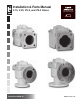
Installation & Parts Manual V-15, V-30, VS-3, and VS-4 Valves Installation: M400-20 www.lcmeter.
Table of Contents Description Page Number General Information ..................................................................... 2 Specifications ............................................................................... 3 Application Class Description ...................................................... 3 V-15 & V-30 Valves ...................................................................... 4-10 General ...........................................................................
Specifications Model Body & Seal Material Companion Flanges Working Pressure Application Class* 1, 16 1, 3, 14 1, 16 3, 4, 14, 15 2, 14, 15 V-15 (A-3600 Series) A3610 A3611 A3612 A3620 A3622 Aluminum with Viton Seal Aluminum with Viton Seal Aluminum with Teflon Seal Aluminum with Viton Seal Aluminum with Teflon Seal Aluminum with Viton Seal 3" 3" 3" 3" 3" 3" 150 PSI (10.3 BAR) 150 PSI (10.3 BAR) 150 PSI (10.3 BAR) 150 PSI (10.3 BAR) 150 PSI (10.3 BAR) 150 PSI (10.
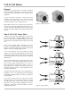
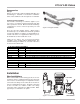
V-15 & V-30 Valves General V-15 valves are designed for use on M-15 and M-25 positive displacement flowmeters; V-30 valves are for use on M-30, M-40, and M-60 positive displacement flowmeters. V-15 & V-30 valve operation is smooth and easy regardless of the line pressure since the vector forces are directed at right angles to the valve opening mechanism and are never in opposition to it.
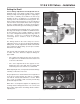
V-15 & V-30 Valves Accessories Flanges Flanges are offered in 3 and 4 inch BSPT and NPT sizes and weld types. Material of construction is aluminum. Teflon, Viton, and Buna seals and gaskets are available. Linkage and Valve Handles Valve handle and linkage assemblies (Figure 3) are accessories used when normal manual ON and OFF valve operation is desired. Different handle and linkage configurations can be ordered separately for field installations.
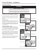
V-15 & V-30 Valves - Installation Retrofit Installations ! WARNING Relieve Internal Pressure All internal pressure must be relieved to zero pressure before disassembly or inspection of the meter or any of the meter accessories. Serious injury or death from fire or explosion could result from maintenance of an improperly depressurized and evacuated system. Depending on the existing configuration, adding a V-15 or V-30 Valve may require modification of the outlet piping.
V-15 & V-30 Valves - Installation Retrofit Installations (continued) Mount the ball joint extension to the preset ring by threading the screw into one of the holes at the back of the register assembly. Thread the nut in place on the screw. With the ball joint extension secure on the preset ring, attach the linkage assembly (Figure 6b). The linkage assembly may require adjustment in order to mount to the ball joint extension.
V-15 & V-30 Valves - Reassembly Disassembling the Valve (continued) 6. Reposition the valve assembly so that the outlet side is facing up. 7. Remove the two screws (Item 615) that hold the guide (Item 138) and seal in place and remove the guide and seal. The valve shaft (Item 368) is not removable, but it is not necessary to remove it in order to inspect or replace the O-Rings and bearings of the valve shaft. 8. Remove the retaining ring (Item 564) from one side of the valve shaft.
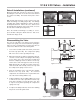
V-15 & V-30 Valves - Installation Setting the Dwell Correct linkage adjustments avoid hydraulic shock. Hydraulic shock occurs when a volume (mass) of liquid moving at a high rate through a pipeline is stopped by a valve that is suddenly closed. When the flow stops abruptly, the mass of liquid acts as a battering ram, causing a shock effect within the metering system. The meter housing and internal parts receive the full impact since the valve is located at the meter outlet.
V-15 & V-30 Valves - Installation Adjusting Zero Shutoff (LC Preset) Because of the interaction between the valve and the preset counter, some adjustment may be needed to the preset counter so that components work at optimum efficiency. Preset Counters assembled with meters at the factory are adjusted for proper shut-off timing. Due to meter system variations, such as flow rate and viscosity, it may be necessary to make zero shut-off adjustments.
VS-3 & VS-4 Valves General VS-3 valves are designed for use on MS-30 and MS-40 steel case, positive displacement flowmeters; VS-4 valves for use on MS-75 steel case, positive displacement flowmeters. VS-3 & VS-4 valve operation is smooth and easy regardless of the line pressure since the vector forces are directed at right angles to the valve opening mechanism and are never in opposition to it.
VS-3 & VS-4 Valves - Installation Accessories Flanges Flanges are offered in 3 and 4 inch BSPT and NPT sizes and weld types. Material of construction is steel. Teflon, Viton, and Buna seals and gaskets are available. Linkage and Valve Handles Valve handle and linkage assemblies are accessories used when normal manual ON and OFF valve operation is desired. Different handle and linkage configurations can be ordered separately for field installations.
VS-3 & VS-4 Valves - Installation Retrofit Installations ! WARNING Relieve Internal Pressure All internal pressure must be relieved to zero pressure before disassembly or inspection of the meter or any of the meter accessories. Serious injury or death from fire or explosion could result from maintenance of an improperly depressurized and evacuated system. Depending on the existing configuration, adding a VS-3 or VS-4 Valve may require modification of the outlet piping.
VS-3 & VS-4 Valves - Disassembling Disassembling the Valve The VS-3 & VS-4 Valves are under pressure from the compression spring. The safest method for opening the valve for service or maintenance is to place the valve on a flat surface with the valve outlet facing down. 1. Loosen the four bolts (Item 611) located on the valve cap (Item 124). The compression spring will exert a force on the cap and push it up. 2.
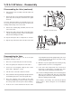
VS-3 & VS-4 Valves - Reassembling Reassembling the Valve For reassembly, refer to Figures 18 & 19 or the parts breakdown on Pages 21 & 23. 1. Place the O-Ring (Item 455) on the guide (Item 354). 2. Place the upper seal (Item 453) and the bonded seal ring (Item 354) onto the guide (Item 138). 3. Place the two retainer ring guides (Item 139) on the guide. 4. Place the guide (Item 138) into the valve. 5. Secure this assembly using the four screws (Items 627) and lock washers (Item 745). 6.
Illustrated Parts Breakdown - V-15 Valves Item No. 110 124 133 138 140 260 270 337 338 354 368 370 382 412 424 450 455 465 541 543 559 564 610 611 615 626 718 727 741 Description Housing Valve Cap Cup Guide Bearing (2) Inner Bearing (2) Shaft Case Seal (2) Link (2) Link Arm Seal Ring Valve Shaft Guide Shaft Compression Spring Cap Casket Flange Gasket O-Ring (2) O-Ring (2) Upper Seal Ring Cotter Pin (4) Tapered Groove Pin Retaining Ring Retaining Ring (2) Screw, .500-13 x 1.50 (2) Screw, .500-13 x 2.
Illustrated Parts Breakdown - V-15 Valves A-3610 Shown 17
Illustrated Parts Breakdown - V-30 Valves Item No. 110 124 133 138 140 260 270 337 338 354 368 370 382 412 450 455 465 541 543 559 564 610 611 615 718 727 741 Description Housing Sub-Assembly Valve Cap Cup Guide Bearing (2) Inner Bearing Guide (2) Shaft Case Seal (2) Link (2) Link Arm Seal Ring Valve Shaft Guide Shaft Compression Spring Flange Gasket (2) O-Ring (2) O-Ring (2) Upper Seal Ring Cotter Pin (4) Tapered Groove Pin Retaining Ring Retaining Ring (2) Screw, .625-11 x 1.75 (6) Screw, .625-11 x 2.
Illustrated Parts Breakdown - V-30 Valves A-4610 Shown 19
Illustrated Parts Breakdown - VS-3 Valves Item No. 110 124 133 138 139 140 260 270 337 338 354 368 370 382 420 450 451 Description Housing Sub-Assembly Cap Sub-Assembly Cup Machined Guide Retainer Ring Guide (2) Bearing (2) Inner Bearing Guide (2) Shaft Case Seal (2) Link (2) Link Arm Seal Ring Cap Shaft Guide Shaft Compression Spring Flange Gasket O-Ring O-Ring (2) *N/S = Not for Sale Model No. Item No.
Illustrated Parts Breakdown - VS-3 Valves A-36501 Shown 21
Illustrated Parts Breakdown - VS-4 Valves Item No. 110 124 133 138 139 140 260 270 337 338 354 368 370 382 420 450 451 453 455 456 533 541 543 559 564 611 614 627 650 718 727 741 745 Description Housing Sub-Assembly Cap Sub-Assembly Cup Machined Guide Retainer Ring Guide (2) Bearing (2) Inner Bearing Guide (2) Shaft Case Seal (2) Link (2) Link Arm Seal Ring Cap Shaft Shaft Guide Compression Spring Flange Gasket O-Ring O-Ring (2) Upper Seal Ring O-Ring O-Ring (2) Nut, .
Illustrated Parts Breakdown - VS-4 Valves A-46501 Shown 23
A Unit of IDEX Corporation 105 Albrecht Drive Lake Bluff, IL 60044-2242 1.800.458.5262 • 847.295.1050 Fax: 847.295.1057 www.lcmeter.com © 2007 Liquid Controls Pub. No.