Translation of the original operating instructions Sensor 01 Type: Liquidtool sensor Product number: LTS-1-01-XXXXXX Year of manufacture: 2021 Follow these instructions for proper and safe use. Keep for future reference.
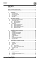
Sensor 01 Contents CONTENTS Contents ............................................................................................................................. 3 Purpose of the operating instructions ............................................................................ 5 Orientation in the operating instructions ....................................................................... 5 1 Identification ...............................................................................................
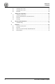
Sensor 01 Contents 6.1 6.2 6.3 6.4 7 Taking out of operation ................................................................................... 29 7.1 7.2 7.3 7.4 8 Introductory safety notes ........................................................................................... 29 Remove the identification of the machine tool ........................................................... 29 Removal ........................................................................................................
Sensor 01 Purpose of the operating instructions PURPOSE OF THE OPERATING INSTRUCTIONS Ensure that you have read the operating instructions before you operate the sensor for the first time or when you are instructed to carry out other work on the sensor. Using and handling the sensor described below is not self-evident. It is explained in detail in the accompanying technical documentation. Take special notice of the chapter "2 Basic safety instructions".
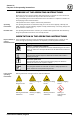
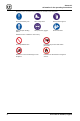
Sensor 01 Orientation in the operating instructions Mandatory icons are used for the prevention of accidents at the workplace General mandatory icon Wear safety shoes Wear protective gloves Wear adequate working clothes Wear protective goggles Read instructions Prohibition icons contribute to more safety.
Sensor 01 Identification 1 IDENTIFICATION 1.1 Product identification Sensor 01 Sensor type: Liquidtool sensor Product number: LTS-1-01-XXXXXX Year of manufacture: 2021 1.2 Manufacturer information Company headquarters Liquidtool Systems Inc. Winterseistrasse 22 3415Hasle-Rüegsau Switzerland E-mail: info@liquidtool.com Internet: www.liquidtool.com Tab. 2: Manufacturer information 1.
Sensor 01 Identification 1.4 Rating plate The rating plate and the product information on the product clearly identify the sensor. The rating plate of the sensor sits on the bottom of the sensor. Fig. 1: Place of attachment 1 Rating plate Fig.
Sensor 01 Identification 1.5 Declaration of Conformity Fig.
Sensor 01 Basic safety instructions 2 BASIC SAFETY INSTRUCTIONS 2.
Sensor 01 Basic safety instructions A specialist is a person who successfully completed vocational training. The specialist must also have knowledge of the applicable relevant standards and regulations. He/she must be able to assess assigned work and, based on his/her professional training and work experience, recognize and avoid potential hazards on his/her own.
Sensor 01 Basic safety instructions WARNING Danger from strong magnets The magnets generate strong electromagnetic fields that can affect and interfere with electronic devices (such as cardiac pacemakers). Malfunctioning cardiac pacemakers can cause death or serious injuries to the persons concerned. Persons with cardiac pacemakers are not allowed to be in the vicinity of the sensor. Persons with cardiac pacemakers are not allowed to work with or handle the sensor.
Sensor 01 Basic safety instructions 2.3.4 Hazards from coolants Hazards from coolants Depending on the currently used coolant, there can be various hazards and risks. Reading the data sheet of the coolant is therefore absolutely necessary! WARNING Health damage from coolant A direct contact of the coolant with the skin can cause diseases and health damage. Direct contact of your eyes with coolant can cause severe irritation of the eyes.
Sensor 01 Basic safety instructions 2.4 Safety instructions of the sensor The sensor is delivered with several pictograms and warnings as stickers. Due to the small size of the product, these stickers can not be attached to the sensor. In the course of the assembly, these stickers must instead be glued on in the vicinity of the sensor, for example on the housing of the machine tool. Ensure that these stickers are checked at regular intervals. Damaged stickers must be replaced immediately. Fig.
Sensor 01 Description, structure and function 3 DESCRIPTION, STRUCTURE AND FUNCTION 3.1 Intended use This sensor may only be used to measure the concentration (via refractive index) and temperature of coolant. The coolant must be emulsifiable in water. The measurement requires the sensor to have access to the coolant tank of a machine tool. Access is established through the inlet and outlet pipes. The app associated with the sensor then collects the acquired data.
Sensor 01 Description, structure and function Connected loads and power – pump Value Unit Operating mode continuous VDC Pump interval Adjustable between 30 and 120 minutes Delivery volume 200 Fluid connection IQS standard 6/8 mm ml/cycle Tab. 6: Connected loads and power – pump Interfaces Communication / interfaces Bluetooth WiFi NFC Tab. 7: Interfaces Emission values Value Sound power level <75 dB(A) A-weighted equivalent continuous sound pressure level is below 70 dB(A) Tab.
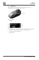
Sensor 01 Description, structure and function Fig. 6: Design of the sensor (rear view) 1 Background lighting 5 Power supply unit connection 2 Recessed grip 6 Inlet connecting fitting 3 Main switch 7 Outlet connecting fitting 4 RS485 interface 3.7 Functional and system description The sensor takes samples of the coolant from the coolant tank via the intake hose. Temperature and concentration of the samples are determined before the samples are returned to the tank via the outlet hose.
Sensor 01 Description, structure and function 3.
Sensor 01 Transportation, installation and storage 4 TRANSPORTATION, INSTALLATION AND STORAGE 4.1 Introductory safety notes Personnel qualification The following personnel are authorized for "transportation, installation and storage": Trained, instructed operating personnel Important information for your safety You are responsible! In any case, ensure that the safety instructions in chapter 2 "Basic safety instructions" and the locally applicable safety regulations are observed and complied with.
Sensor 01 Transportation, installation and storage 4.4 4.4.1 Delivery Scope of delivery The scope of delivery contains: Fig. 7: Scope of delivery 4.4.2 1 Connecting cable with power supply unit 2 Outlet hose (including weight) 3 Intake hose (including filter) 4 Sensor 01 5 Safety information and warnings Checking for transportation damage Check the sensor for transportation damage immediately after it has been delivered to the installation location.
Sensor 01 Transportation, installation and storage 4.5 Downloading the app The sensor is controlled and used via a specifically developed app (Coolant Manager). The app can be downloaded and installed via a smartphone. Use the following procedure to download the app: 1. Scan the QR code below with an appropriate app/camera of your smartphone. Fig. 8: QR code to download the app 2. 3. 4.6 Your smartphone asks you whether you want to open the link. Open the link.
Sensor 01 Startup 5 STARTUP 5.1 Introductory safety notes Personnel qualification The following personnel are approved for "Startup": Trained, instructed operating personnel Specialists for special work on machine tool, cooling lubricant tank or electrical system Important information for your safety You are responsible! In any case, ensure that the safety instructions in chapter 2 "Basic safety instructions" and the locally applicable safety regulations are observed and complied with.
Sensor 01 Startup 5.3 Identification of the machine tool To enable you to easily and securely identify the monitored machine tool, the sensor is equipped with a removable, magnetic NFC token with integrated NFC (RFID). You can attach it to any metallic magnetic surface. Mark the machine tool you want to monitor before connection and startup. Use the following procedure to mount the magnetic NFC token on the machine tool: 1. Detach the NFC token from the sensor. Fig.
Sensor 01 Startup 5.5 Connection Requirement: The machine tool was marked The information about the connection was read and understood 1 copy of each warning and safety instruction is available Use the following procedure to connect the sensor: 1. Remove the plugs (2) from the hose lines. To do this, press the metal coupling rings (1) in the direction of the sensor while you are pulling out the plugs (2). Fig. 11: Removing the plugs 2. Connect the power cable provided to the sensor.
Sensor 01 Startup 3. Connect the hose lines provided to the sensor. To do this, press the metal coupling rings (1) in the direction of the sensor while you are inserting the hose lines (2) into the bushings. Release the coupling ring. The coupling ring moves back to its initial position, thus locking the hose line. The left connection is for the hose line with pump. The right connection is for the outlet hose Fig. 13: Connecting the connecting lines Fig. 14: hose lines connected 4.
Sensor 01 Startup 6. You will notice whether or not the magnets are holding the sensor. The surface is not suitable for attachment if the magnets do not hold the sensor. Find another surface and repeat the previous step. 7. CAUTION! Risk of injury from dropping sensor! Release the sensor only slowly. This allows you to see whether or not it is slipping or moving. Hold on to the sensor if it slips or moves. You can thus prevent minor injuries to your feet and damage to the sensor.
Sensor 01 Startup 10. Check the filter of the intake hose. It must not be in contact with the bottom of the tank. To obtain optimum results, the suction filter should be completely surrounded by coolant. Fig. 18: Correctly routed hose lines 11. Insert the mains plug into a suitable socket outlet. The connection of the sensor is completed. Download the app now.
Sensor 01 Operation 6 OPERATION 6.1 Introductory safety notes Personnel qualification The following personnel are approved for "operation": Trained, instructed operating personnel for using the sensor within the scope of the intended use Important information for your safety You are responsible! In any case, ensure that the safety instructions in chapter 2 "Basic safety instructions" and the locally applicable safety regulations are observed and complied with.
Sensor 01 Taking out of operation 7 TAKING OUT OF OPERATION 7.1 Introductory safety notes Personnel qualification The following personnel are approved for "taking out of operation": Trained, instructed operating personnel for activities on the sensor. Specialists for special work on machine tool, coolant tank or electrical system.
Sensor 01 Taking out of operation 7.3 Removal Requirement: The identification was removed from the machine tool The information about taking the unit out of operation was read and understood The sensor is switched off Wear the necessary personal protective equipment (PPE) Take the information on the data sheet of the coolant into account Absorbent paper Use the following procedure to remove the sensor: 1. 2. Pull the mains plug out of the socket outlet.
Sensor 01 Taking out of operation 7. 8. A manual measurement is started. The sensor is emptied. After a few seconds, the pump should run dry and sound different. This shows that there is no more coolant in the sensor. Now, remove the outlet hose from the coolant tank. Pull the sensor off the surface. It is attached with magnets only. It can be pulled off with some force. Fig. 22: Removing the sensor from the surface Fig. 23: Sensor with hose lines 9. CAUTION! Risk of injuries from leaking coolant.
Sensor 01 Service and maintenance 7.4 Cleaning Requirement: The sensor is switched off A mobile terminal with installed app (mobile) Wear the necessary personal protective equipment (PPE) Take the information on the data sheet of the coolant into account Cleaning of the sensor outside: Clean the surfaces of the sensor with a cloth slightly moistened with soapy water No moisture must get into the sensor when cleaning it.
Sensor 01 Disposal 9 DISPOSAL 9.1 Introductory safety notes Personnel qualification The following personnel are approved for "disposal": Trained, instructed operating personnel Only instructed and authorized skilled electricians are allowed to carry out electrical work Important information for your safety You are responsible! In any case, ensure that the safety instructions in chapter 2 "Basic safety instructions" and the locally applicable safety regulations are observed and complied with.