
Operating Instructions


Sensor 01
Description, structure and function
Print version 03/2021, English
17
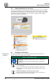
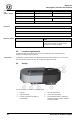
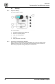
Fig. 6: Design of the sensor (rear view)
1
Background lighting
2
Recessed grip
3
Main switch
4
RS485 interface
5
Power supply unit connection
6
Inlet connecting fitting
7
Outlet connecting fitting
3.7 Functional and system description
The sensor takes samples of the coolant from the coolant tank via the intake hose. Temperature
and concentration of the samples are determined before the samples are returned to the tank
via the outlet hose. The measuring results are transmitted to the Liquidtool Manager and stored
there.
The temperature of the coolant is measured directly in the flow channel.
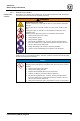
3.8 LED status indicator
There is an LED in the capacitive button on the front of the product. This LED shines in different
colors, indicating the status of the product. You can find more information about this in the
Liquidtool app.
Color
State
Description/meaning
White
Shines continuously
The product is switched on
Green
Shines continuously
The product is ready for operation
Blue
Shines continuously
Interaction necessary
Blue
Blinking
The sensor is working (measurement in progress,
or software is updated)
Orange
Shines continuously
Information: The measured value is outside the
specification
Red
Shines continuously
Fault/malfunction
Tab. 9: Status indicator LED